


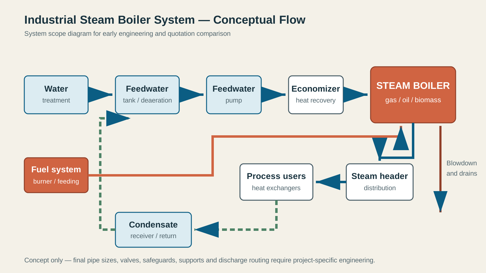
What an industrial steam boiler system diagram should show
Show treatment → feedtank → pump → economizer → boiler, then steam header → users → condensate return. Include dosing, blowdown, drains, vents, safety-valve discharge, fuel and flue gas.
This is a conceptual system diagram. A construction piping drawing also needs pipe sizes, slopes, supports, expansion provisions, valve ratings and instrument details.
1. Water treatment and feedwater preparation
Select treatment from raw-water analysis and boiler pressure. Combine treated makeup and suitable condensate in the feedwater system. Specify deaeration and chemical dosing for the agreed water-quality limits.
Confirm whether the supply includes treatment, feedtank, pumps, dosing and water-quality instruments.
2. Feedwater pump and economizer
Size feed-pump differential head from boiler pressure, suction pressure, elevation and feed-line losses. Check NPSH at hot-feedwater conditions. Maintain the required flow through the economizer without steaming.
3. Boiler, burner and combustion controls
For a gas-fired steam boiler, the burner, gas train, combustion-air fan, flame safeguard and boiler controls operate as one safety sequence. Fuel pressure, turndown, oxygen availability and furnace resistance influence burner selection. Oil-fired and dual-fuel systems add pumps, heaters or atomization equipment as required by the liquid fuel. See the gas, oil and dual-fuel steam boiler burner selection guide for the project inputs and supply boundaries.
A biomass steam boiler uses a different fuel path: storage, conveying, metering, grate or combustion chamber, ash handling and particulate control. Fuel moisture, particle size and ash behavior must be defined before equipment selection.
4. Steam header, process users and pressure control
The boiler outlet connects to a main steam header sized for the peak coincident load and acceptable pressure drop. Branches should be arranged to deliver dry steam, manage drainage and isolate process areas safely. Pressure-reducing stations may be needed when users require different pressures. Steam quality matters: excessive moisture can reduce heat-transfer performance and damage control valves or equipment.
5. Condensate return and heat recovery
Clean condensate retains heat and treated water. Returning it can reduce makeup-water demand, treatment chemicals and fuel use. The actual return rate depends on process contamination risk, pressure levels, distance and the way traps and receivers are arranged. A flash-steam recovery arrangement may be considered where higher-pressure condensate is discharged to a lower-pressure receiver.
6. Blowdown, drains and safety discharge
Continuous and intermittent blowdown control dissolved and suspended solids. The discharge may require a blowdown vessel, cooling or heat recovery before it reaches the site drainage system. Safety-valve discharge piping must be routed and supported so it does not impose damaging loads on the valve or boiler connection. These lines should never be improvised from a simplified marketing diagram.
Capacity and fuel data needed before detailed piping design
- Steam demand by user, peak simultaneous load and operating schedule
- Required steam pressure and any superheat or dryness requirement
- Feedwater temperature, makeup-water analysis and expected condensate-return percentage
- Natural-gas pressure/composition, liquid-fuel grade or biomass properties
- Project altitude, ambient range, electrical supply and installation constraints
- Applicable emission, inspection and documentation requirements
- Desired supply boundary: boiler-only, packaged equipment or complete boiler house
Once these values are known, a preliminary mass and energy balance can support boiler capacity, fuel consumption, pump duty, treatment capacity, heat recovery and major pipe sizing.
How this guide supports a purchase decision
Searches such as “industrial steam boiler system diagram,” “industrial steam boiler piping diagram,” “industrial steam boiler price” and “industrial steam boiler manufacturers” often come from different stages of the same project. The diagram defines what belongs in the plant; the process data defines the capacity; and a common supply boundary makes quotations comparable.
Equipment: gas-fired steam boiler and biomass steam boiler. Sizing: industrial steam boiler selection guide.