


Gas / oil-fired thermal oil heater
2.4–14 MW preliminary range, up to 320 °C. Confirm gas composition and pressure or liquid-fuel specification, then match the burner to useful heat duty, fluid temperatures and circulation.
THERMAL OIL HEATER MANUFACTURER IN CHINA
JIELI manufactures thermal oil heaters in Linyi, China, also specified as thermal fluid or thermic fluid heaters. Compare gas and oil-fired models with biomass systems using heat duty, oil temperatures and circulation data. Send your fuel and project country to start a quotation.
THERMAL OIL PRODUCT FAMILY
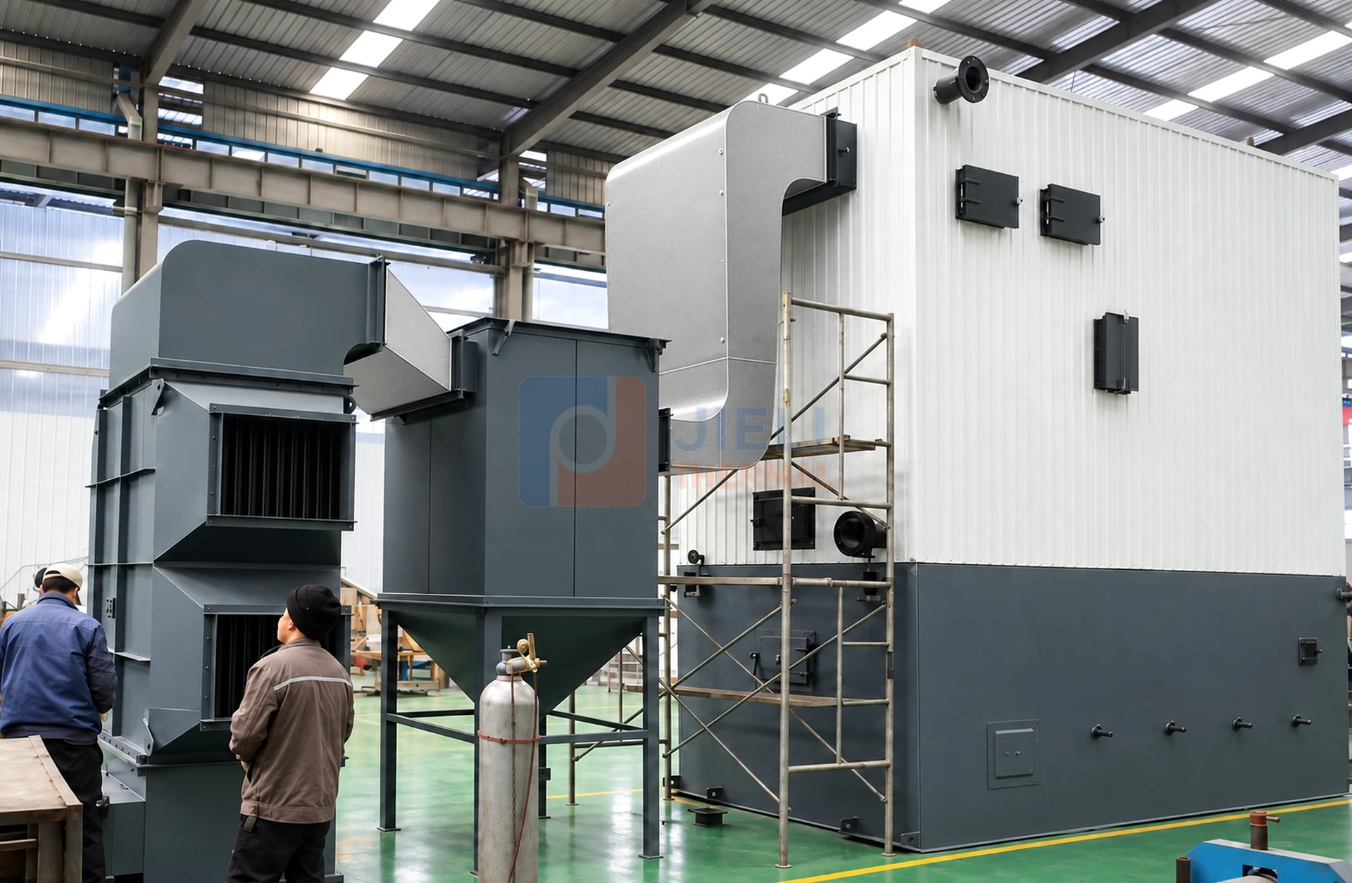
Choose a fuel route using the fuel available at your plant, its delivered cost and the required load profile. Gas and liquid fuels need a defined burner supply; biomass needs representative fuel analysis and space for storage, feeding and ash handling. Compare the heater and its auxiliaries on the same useful heat-duty basis.
2.4–14 MW preliminary range, up to 320 °C. Confirm gas composition and pressure or liquid-fuel specification, then match the burner to useful heat duty, fluid temperatures and circulation.
1.4–24 MW preliminary range, up to 320 °C. Specify biomass moisture, size, ash and heating value. Storage, feeding, furnace, grate, dust and ash equipment must match that fuel basis.
1.4–24 MW preliminary range, up to 320 °C. Combustion and environmental scope must be selected from coal properties and destination-country requirements.
THERMAL OIL HEATER SPECIFICATIONS
This matrix brings the current JIELI thermal oil heater families onto one comparable basis. It is a preliminary selection reference—not a substitute for thermal-fluid properties, process duty, circulation calculations, fuel analysis, site conditions or applicable code.
These are published family ranges, not a guarantee that every fuel or operating condition is suitable across the full range. Use the linked product data and confirm the proposed model against your project inputs.
| Thermal oil heater route | Series designation | Published preliminary range | Maximum temperature | Fuel basis |
|---|---|---|---|---|
| Gas / oil-fired thermal oil heater | YY(Q)W · YQW · YY(Q)L · YQL | 2.4–14 MW | Up to 320 °C | Natural gas, diesel or project-confirmed fuel oil |
| Biomass thermal oil heater | YLW · YGL · YLL | 1.4–24 MW | Up to 320 °C | Wood chips, pellets and project-approved agricultural residues |
| Coal-fired thermal oil heater | YLW · YGL · YLL | 1.4–24 MW | Up to 320 °C | Project-specified coal analysis |
Published ranges summarize the current linked product pages. Final model, usable duty, temperature and system boundary are project-specific.
THERMAL OIL HEATER PROJECT REFERENCES
Compare the project stage as well as capacity and fuel. The YLW250, 2,800 kW Surabaya project gallery documents workshop equipment and an illustration for an Indonesian biomass project; it does not establish commissioned performance. The references below show other installation or delivery stages, not interchangeable design specifications.
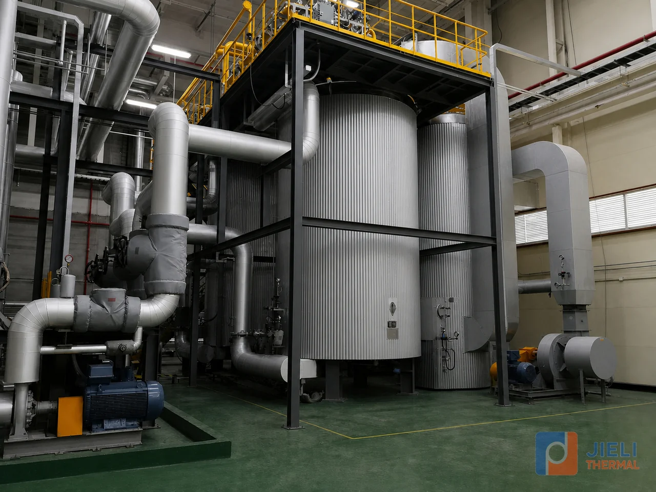
Gas-fired thermal oil heater installed for controlled heat supply to a new-energy battery production process.
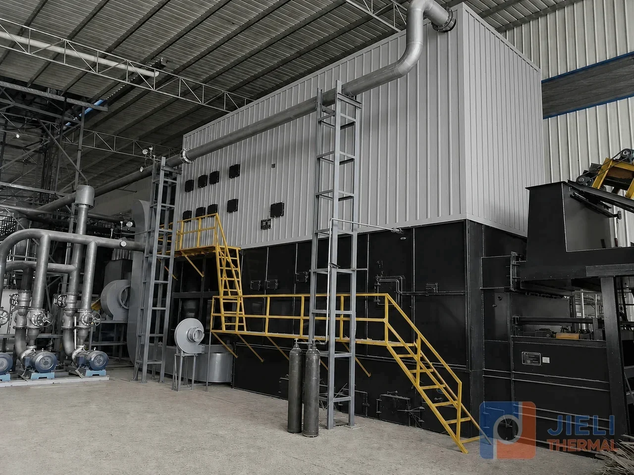
Biomass thermal oil heater installation documented with fuel handling, service access and connected auxiliaries.
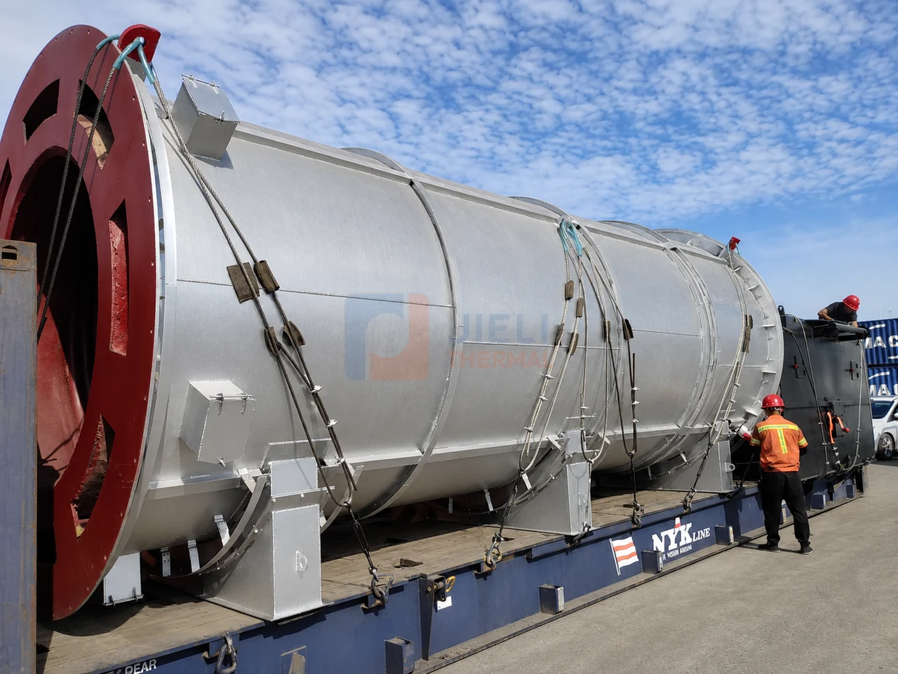
Wood-chip biomass thermal oil heater and combustion equipment documented during secured export loading.
HOW A THERMAL OIL HEATER WORKS
A thermal oil heater transfers heat from a burner or solid-fuel furnace into a continuously circulating heat-transfer fluid. The hot fluid flows to reactors, dryers, presses, tanks or other process users, releases useful heat and returns to the heater for reheating.
The system is engineered as one loop: heater coil, circulation pumps, expansion and storage vessels, piping resistance, process users, controls and safety interlocks. Selection therefore begins with heat duty, supply and return temperatures, fluid limits, circulation demand, fuel and site conditions—not with a catalogue capacity alone.
The burner or solid-fuel furnace supplies energy to the heater coil while controls protect minimum flow, outlet temperature and the selected thermal fluid's film-temperature limit.
Pumps move hot thermal fluid through the distribution loop. Flow, pressure drop and branch balancing are checked at operating temperature for the actual plant arrangement.
The cooled fluid returns for reheating while the expansion system accommodates volume change and supports venting, storage, pump suction and safe startup.
PROCESS-HEATING DECISION
A thermal oil heater can deliver stable indirect heat at elevated temperature with a liquid circulation loop and generally lower system pressure than an equivalent high-temperature steam system. It is not automatically the right choice for every plant; the process must be checked first.
| Process requirement | Potential thermal-oil advantage | Engineering check before selection |
|---|---|---|
| High process temperature | Liquid-phase heat transfer can serve many duties in the 180–320 °C range without generating high-pressure steam. | Confirm the selected fluid’s maximum bulk and film temperatures, oxidation limits and heater heat flux. |
| Stable indirect control | A closed circulation loop can provide controlled heat to reactors, dryers, presses, tanks and exchangers. | Define supply and return temperatures, turndown, simultaneous users and control-valve behaviour. |
| Several distributed heat users | One properly engineered loop can distribute heat to multiple branches and production areas. | Calculate hot-fluid flow, pressure drop, branch balancing, minimum heater flow and pump NPSH. |
| Lower pressure at high temperature | The loop normally operates at much lower pressure than steam would require at the same temperature. | Design pressure still includes pump head, static head, expansion arrangement and the applicable project code. |
| Lifecycle and maintenance | No steam traps, condensate return or boiler-water treatment is needed for the thermal-oil loop. | Plan fluid sampling, filtration, leak prevention, fire protection, expansion management and controlled startup. |
When steam may be better: choose steam when the process consumes steam directly, requires humidification or sterilization, or already has a practical condensate and water-treatment infrastructure. Compare the complete systems—not only the heater or boiler body.
BUYER MODEL TERMINOLOGY
A series designation helps identify the fuel route and heater arrangement. Compare the proposed coil geometry, rated heat duty, circulation requirements and layout with the linked product data before accepting the model selection.
| Series or product designation | Arrangement to confirm | Relevant JIELI route |
|---|---|---|
| YY(Q)W / YQW thermal oil heater | Horizontal gas- or oil-fired arrangement; confirm the proposed coil layout and burner duty. | Gas / oil-fired thermal oil heater |
| YY(Q)L / YQL thermal fluid heater | Vertical gas- or oil-fired arrangement; confirm the required height and maintenance access. | Gas / oil-fired thermal fluid system |
| YLW biomass thermal oil heater | Horizontal grate-fired arrangement; match the furnace, feeding and ash systems to the analyzed solid fuel. | Biomass route · Coal route |
| YGL / YLL hot oil boiler | Solid-fuel series labels; verify the actual orientation, coil construction and fuel-feed arrangement in the proposal. | Configuration must be confirmed against fuel, capacity, layout and applicable code. |
Procurement note: series naming can vary by manufacturer and specification. Compare the actual heater geometry, rated duty, design temperature and pressure, minimum circulation, fuel equipment, controls, emissions scope and documentation—not the model code alone.
SELECTION DATA
A useful quotation starts with the process. Send the information below so the heater and circulation loop can be checked on one basis.
| Input | Why it matters |
|---|---|
| Heat duty and load profile | Defines normal, peak and minimum firing demand and sensible design margin. |
| Supply / return temperature | Determines useful temperature difference, fluid properties and required flow. |
| Thermal fluid | Viscosity, density, heat capacity, film-temperature limit and compatibility affect the loop. |
| Process pressure drop | Used with piping and heater resistance to select circulation pumps. |
| Fuel and site | Fuel properties, altitude, ambient conditions, emissions and utilities change the configuration. |
| Supply boundary | Separates heater-only price from pumps, tanks, controls, heat recovery and project interfaces. |
CAPACITY & UNIT GUIDE
Use one heat-duty basis when comparing a thermal oil heater, thermal fluid heater or hot oil boiler. The values below are unit conversions—not final model selections. Operating temperature, fluid properties, circulation, pressure drop, fuel and design margin still have to be checked.
| Capacity designation | MW | Approx. kcal/h | Approx. MMBtu/h |
|---|---|---|---|
| 1,000 kW | 1.00 MW | 860,000 kcal/h | 3.41 MMBtu/h |
| 2,000 kW | 2.00 MW | 1,720,000 kcal/h | 6.82 MMBtu/h |
| 3,500 kW | 3.50 MW | 3,009,000 kcal/h | 11.94 MMBtu/h |
| 5,000 kW | 5.00 MW | 4,299,000 kcal/h | 17.06 MMBtu/h |
| 10 MW | 10.00 MW | 8,598,000 kcal/h | 34.12 MMBtu/h |
| 15 MW | 15.00 MW | 12,898,000 kcal/h | 51.18 MMBtu/h |
A 2,000,000 kcal/h thermal oil heater is approximately 2.33 MW; 5,000,000 kcal/h is approximately 5.81 MW. The published South Korea 5,000,000 kcal/h gas-fired project provides an installed-system reference at the latter duty. Match your fluid, supply and return temperatures, circulation and fuel conditions before selecting a similar system.
ENGINEERING VERIFICATION
A reliable thermal oil heater is selected from the complete hot-oil loop. Coil diameter, pass arrangement, local heat flux, thermal-fluid properties and circulation rate are checked at operating temperature and at the lowest stable load. There is no universal velocity or film-temperature number that is safe for every fluid and every heater.
Design boundary: final values are confirmed from the selected thermal-fluid supplier data, process duty, pipe routing, site elevation and applicable project code before manufacture.
Hydraulic calculation checks flow through each coil pass, pressure drop and minimum circulation. The aim is to avoid stagnant or low-flow zones while keeping pump power and erosion within the project design envelope.
The fluid supplier's maximum bulk and film temperatures are treated separately. Radiant and convection heat transfer, coil surface temperature and control margin are reviewed so the thermal fluid is not exposed to avoidable cracking or carbon formation.
Pump selection uses hot-fluid density, viscosity and vapour pressure together with system resistance, static head and expansion-tank elevation. Available NPSH and the operating-point margin are verified for the actual layout.
Typical logic coordinates pump status, flow or differential-pressure permissive, outlet temperature, expansion-tank level and burner or fuel-equipment shutdown. The agreed cause-and-effect list is project-specific.
COMPLETE THERMAL OIL SYSTEM
A complete thermal oil system can include the heater, burner or solid-fuel equipment, circulation pumps, expansion and storage vessels, heat users, control and safety instruments, heat recovery, chimney and project piping interfaces. Final scope is project-specific.
Pump duty, hot-fluid properties, pressure drop, control-valve behavior and minimum-flow protection must work together.
System volume, operating temperature, thermal expansion and drain-back requirements determine vessel sizing and arrangement.
Flow, temperature, pressure, level, burner or fuel equipment and emergency logic should be coordinated as one operating system.
PROCESS APPLICATIONS
Common applications include chemical reactors and distillation, textile printing and dyeing, plywood and wood-panel pressing, asphalt and bitumen, food frying and drying, plastics and rubber, pharmaceuticals and other processes needing stable indirect heat.
Review process temperature, hazardous-area requirements, heat-user pressure drop and control response. For an installed indirect-heating reference, see the South Korea battery-process thermal oil heater; its project record identifies the duty and application, while your process data determines the final design.
Coordinate dryers, stenters, calenders and other users with the total plant load profile.
Separate tank heat-up, holding losses, piping, unloading and simultaneous users before selecting the thermal oil heater.
BUYER KNOWLEDGE
Use these guides to prepare comparable project data and evaluate a thermal oil heater manufacturer beyond the catalogue price.
Heat duty, temperatures, fluid, fuel, circulation and system boundary.
Flow, head, hot-fluid properties, operating points and minimum-flow protection.
Compare evidence, inspection, controls, system integration, documents and lifecycle scope.
Normalize heater-only and complete-system offers across equipment, services, project interfaces and operating cost.
Connect panel throughput, press cycles, heat duty, temperature and branch hydraulics.
Plan charging, cold circulation, moisture removal, safeguard tests and handover.
Interpret viscosity, TAN, moisture, insolubles and boiling-range changes as one trend.
Clarify thermal oil heater, thermal fluid heater and hot oil boiler terminology before comparing specifications.
Connect heat duty, biomass fuel, circulation, emissions and project location for Malaysian applications.
PROJECTS & LOCAL-LANGUAGE SUPPORT
A biomass proposal should use the actual wood-chip, pellet or agricultural-residue analysis. Compare the Chile biomass thermal oil heater and Thailand installation with your duty, fuel handling and shipment constraints; a reference is not a substitute for project selection.
The regional guides explain which fuel, site, emissions and supply-scope details to send with your enquiry. Use the model tables and project photographs below when discussing the equipment.
MANUFACTURING & PROJECT RECORDS
Review the coil-forming, welding and assembly records alongside the proposed manufacturing route. Ask the supplier to identify the material records, inspection points, control checks and packing documents included in your order. Photographs show equipment and production stages; the agreed inspection records establish what was verified for the supplied unit.
Review pressure-part preparation, coil forming, welding, assembly, controls and inspection in the Linyi manufacturing base.
Compare documented biomass, gas and coal-fired projects by capacity, country, installation and export stage.
Define circulation, expansion, fuel equipment, heat recovery, controls, emissions scope and project interfaces together.
THERMAL OIL HEATER SUPPLIER CHECKLIST
A useful thermal oil heater proposal states the design basis, calculation boundary, equipment scope and verification documents. This lets buyers compare manufacturers on the same heat duty, temperature, fuel, circulation and delivery basis instead of comparing incomplete headline prices.
Rated, normal and minimum duty, supply and return temperature, thermal-fluid data, fuel specification and stated design margin.
Coil arrangement, minimum circulation, pressure drop, pump duty, hot-fluid properties and bulk- and film-temperature limits.
Burner or grate selection, fuel handling, heat recovery, draft system, dust or emissions equipment and the guaranteed boundary.
Instrument list, control architecture, pump permissives, low-flow protection, temperature trips, tank levels and agreed cause-and-effect logic.
Applicable material records, welding procedures and qualifications, inspection plan, nondestructive examination, pressure testing and code documentation as specified by contract.
General arrangement, equipment list, shipping split, installation interfaces, startup support, operator training, spare parts and final document index.
THERMAL OIL HEATER FAQ
These answers define the preliminary selection basis. Final equipment and system scope remain project-specific.
Open the manufacturer evaluation checklistA thermal oil heater transfers heat to a circulating heat-transfer fluid for indirect industrial process heating. The heater, circulation pumps, expansion and storage vessels, controls, process users and safeguards must be selected as one closed-loop system.
A thermal oil heater can deliver stable indirect heat at elevated temperature with a circulating liquid loop and generally lower system pressure than steam would require at the same temperature. Steam may still be preferable when the process consumes steam directly, so compare the complete process and utility systems.
Buyers often use these terms for the same industrial heating-system family. “Thermic fluid heater” is especially common in India and parts of South Asia, while consultant specifications frequently use “thermal fluid heater.” The exact equipment configuration still depends on heat duty, supply and return temperatures, thermal-fluid limits, circulation, fuel, site conditions and the required supply boundary.
JIELI configures gas and oil-fired, biomass-fired and coal-fired thermal oil heater systems. The burner or solid-fuel furnace, fuel handling, emissions equipment and controls are selected from the confirmed fuel specification and destination-country requirements.
Provide normal and peak heat duty, supply and return temperatures, thermal-fluid data, process and piping pressure drop, operating schedule, fuel specification, project country, altitude, ambient conditions, emissions limits, layout and requested supply scope.
Compare verifiable manufacturing and project evidence, coil and circulation calculations, fluid-temperature limits, controls and protection logic, inspection and documentation, auxiliary scope, commissioning support and the stated design boundary—not catalogue price alone.
The current preliminary product pages publish 2.4–14 MW for gas or oil-fired thermal oil heaters and 1.4–24 MW for biomass- or coal-fired thermal oil heaters, with maximum thermal-fluid temperature up to 320 °C. Final capacity, temperature, circulation and system scope are confirmed from project data.
YY(Q)W / YQW commonly refers to a horizontal gas- or oil-fired thermal oil heater; YY(Q)L / YQL is used for vertical gas- or oil-fired configurations; and YLW / YGL / YLL terms are commonly associated with solid-fuel thermal oil heater arrangements. The final configuration must still be checked against fuel, capacity, layout, circulation and applicable code.
The term hot oil boiler is used in some markets, but a thermal oil heater normally heats and circulates a liquid heat-transfer fluid without boiling it to make steam. The complete loop includes the heater, pumps, expansion and storage vessels, controls and process users.
A comparable proposal should state the heat-duty and fuel basis, thermal-fluid temperatures, coil and circulation calculations, pump duty, combustion and emissions scope, control and protection logic, applicable quality and inspection documents, equipment list, delivery interfaces and commissioning boundary.
Integrated package
Need an integrated gas or oil package? Review the skid-mounted thermal oil heater topic for equipment scope, site connections, layout and quotation inputs.
STARTUP & SYSTEM SUPPORT
JIELI’s original thermal oil boil-out notes explain pressure fluctuations, pump behavior and expansion-tank level. Review the staged observation example with your commissioning team and download the startup observation log.
ENGINEERING INPUTS
Start with approximate heat duty, required oil temperature, available fuel and project country. If a value is not known, say so. We can identify the remaining selection inputs and define whether your proposal should include the heater alone or pumps, tanks, controls and heat recovery.