


Engineering features
- Three-pass and application-specific heater configurations
- Integrated burner and combustion control options
- Circulation and expansion systems engineered as one package
- PLC/HMI control architecture available
Thermal Oil Heater
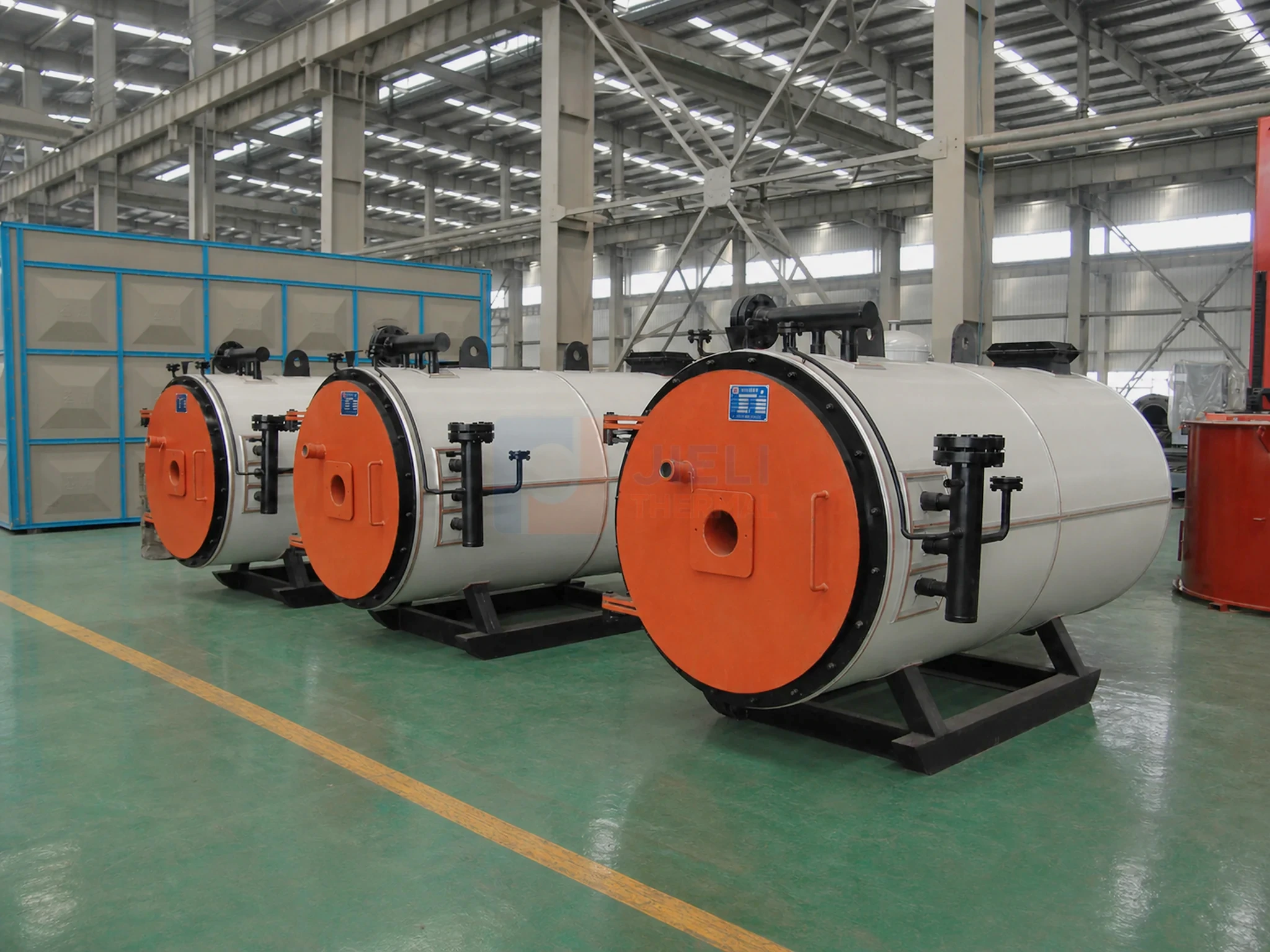
JIELI manufactures gas-fired thermal oil heaters for indirect process heating. Compare the published 2.4–14 MW vertical-series data, oil circulation and project references. Natural-gas, diesel and fuel-oil configurations are reviewed against your heat duty, supply/return temperatures and required system scope.
System overview
JIELI manufactures gas-fired and oil-fired thermal oil heaters for indirect process heating. A thermal fluid heater or thermic fluid heater request should state useful heat duty, oil supply and return temperatures, and the selected fluid. Compare the published gas/oil heater parameters; for an integrated package, review the skid-mounted thermal oil heater scope. Burner, circulation pumps, expansion and storage tanks, controls and heat recovery are coordinated around the actual site.
Equipment and project gallery
JIELI THERMAL equipment and manufacturing views. The Poland skid-mounted image is a digitally retouched product presentation with altered workshop background and finishes, not an unaltered site record. Select an image to read its description.
Project references by rated capacity: United States 1,000,000 kcal/h, South Korea 5,000,000 kcal/h and Saudi Arabia 10,000,000 kcal/h.
Technical parameters
The table below is translated from the technical data supplied for this product family. Final selection is confirmed against your fuel, operating conditions and project requirements.
| Vertical-series model | Rated power | Catalogue oil flow |
|---|---|---|
| YY(Q)L-200Y(Q) | 2,400 kW | 160 m³/h |
| YY(Q)L-400Y(Q) | 4,600 kW | 250 m³/h |
| YY(Q)L-600Y(Q) | 7,000 kW | 400 m³/h |
| YY(Q)L-1200Y(Q) | 14,000 kW | 600 m³/h |
Selected vertical-series catalogue entries, not a pump-sizing calculation. Final oil flow, hot-fluid pressure drop, pump head and fluid limits must be confirmed. Horizontal and skid-mounted layouts require their own configuration review.
Request a model and price check →| Technical parameter | Unit | YY(Q)L-200Y(Q) | YY(Q)L-240Y(Q) | YY(Q)L-300Y(Q) | YY(Q)L-350Y(Q) | YY(Q)L-400Y(Q) | YY(Q)L-500Y(Q) | YY(Q)L-600Y(Q) | YY(Q)L-700Y(Q) | YY(Q)L-800Y(Q) | YY(Q)L-900Y(Q) | YY(Q)L-1000Y(Q) | YY(Q)L-1200Y(Q) |
|---|---|---|---|---|---|---|---|---|---|---|---|---|---|
| Rated heating capacity | ×10⁴ kcal/h | 200 | 240 | 300 | 350 | 400 | 500 | 600 | 700 | 800 | 900 | 1000 | 1200 |
| Rated heating power | kW | 2400 | 2800 | 3500 | 4100 | 4600 | 6000 | 7000 | 8200 | 9300 | 10500 | 12000 | 14000 |
| Rated heating power (converted) | MMBtu/h | 8.19 | 9.55 | 11.94 | 13.99 | 15.70 | 20.47 | 23.88 | 27.98 | 31.73 | 35.83 | 40.95 | 47.77 |
| System thermal efficiency | % | 91.71 | 92.08 | 92.34 | 92.22 | 92.3 | 92.35 | 92.56 | 92.45 | 92.5 | 92.52 | 92.56 | 92.5 |
| Rated working pressure | MPa | 1 | 1 | 1 | 1 | 1 | 1 | 1 | 1 | 1 | 1 | 1 | 1 |
| Maximum working temperature | °C | 320 | 320 | 320 | 320 | 320 | 320 | 320 | 320 | 320 | 320 | 320 | 320 |
| Heater oil capacity | m³ | 2.13 | 3.29 | 3.3 | 4.2 | 4.7 | 6.1 | 7.9 | 9.2 | 10.9 | 11 | 12.3 | 14.5 |
| Circulation flow rate | m³/h | 160 | 200 | 200 | 250 | 250 | 300 | 400 | 400 | 500 | 500 | 500 | 600 |
| Main pipe size | mm | 200 | 200 | 200 | 250 | 250 | 250 | 250 | 300 | 300 | 300 | 350 | 400 |
| Whole-system installed power | kW | 70 | 70 | 90 | 90 | 90 | 120 | 120 | 150 | 150 | 158 | 158 | 200 |
| Overall length | mm | 2450 | 2650 | 2800 | 3480 | 3580 | 3640 | 3750 | 3850 | 3960 | 4120 | 4450 | 4650 |
| Overall width | mm | 2300 | 2500 | 2600 | 3210 | 3210 | 3340 | 3210 | 3520 | 3630 | 3970 | 4100 | 4100 |
| Overall height | mm | 5710 | 6250 | 6970 | 8100 | 8100 | 9350 | 9350 | 9700 | 11000 | 11500 | 12100 | 12300 |
Values are translated from the supplied technical parameter sheets and are intended for preliminary selection. Product data may be updated as designs evolve; final performance, dimensions and configuration are subject to the confirmed technical proposal.
GAS-FIRED PROCESS HEATING
A gas-fired thermal oil heater supplies indirect heat to reactors, dryers and heat exchangers through a circulating liquid. For this thermal fluid heating system, specify useful heat output at the process, operating hours and simultaneous loads rather than selecting from burner input alone.
JIELI coordinates the heater coil, burner, circulation pumps, expansion tank, controls and heat-recovery interfaces around that duty. Use the South Korea gas-fired thermal oil heater project to review equipment and installation context, then confirm the fuel supply and scope required for your own plant.
Selection starts with data
Compare useful heat duty, outlet and return temperatures, gas pressure, burner turndown and emissions requirements. The heater-body price does not include every pump, tank, control, heat-recovery device or site service. Request itemized equipment and exclusions using the thermal oil heater price and quotation guide; compare operating cost on the same fuel heating value and annual hours.
Buyer terminology
These names usually describe the same type of closed-loop liquid-phase process-heating system. The heater raises the temperature of a heat-transfer fluid, circulation pumps move it to process users, and the fluid returns for reheating. The selected fluid, design temperature and system arrangement—not the label alone—define the engineering.
This is the most common name in international industrial purchasing. “Thermal oil” normally means a mineral or synthetic heat-transfer fluid operated below its boiling range.
Consultants often use this broader term because the circulating medium may be a thermal oil or another engineered heat-transfer fluid. It describes the same heater-and-loop concept.
This commercial phrase is widely understood, although the fluid normally remains liquid and does not boil. A quotation still needs the operating temperature, fluid data, heat duty, fuel and site conditions.
Read the detailed thermal oil heater, thermal fluid heater and hot oil boiler terminology guide, or compare this system with an industrial steam boiler.
Terminology FAQ
Usually yes. Both terms commonly describe a fired or electric heater that circulates a liquid heat-transfer fluid through a closed process loop. Confirm the actual fluid, temperature range and design basis in the proposal.
Normally no. “Hot oil boiler” is a market term; most industrial systems keep the heat-transfer oil in the liquid phase. Expansion volume, pump suction conditions and high-temperature safeguards still require project-specific design.
Provide heat duty, supply and return temperatures, thermal-fluid type, fuel specification, operating schedule, process application, project country, altitude, electrical supply, emissions limits and available layout.
COMPLETE SYSTEM REVIEW
The final supply scope is confirmed against fuel, process, site, code and installation responsibilities. These categories make quotations easier to compare. Review the project-specific thermal-fluid engineering basis for film temperature, circulation, NPSH and low-flow protection before fixing the heater model.
Heater body, burner or fuel equipment, insulation and mounted instruments.
Pump duty, standby philosophy, valves, strainers, bypass and branch balancing.
Expansion volume, elevation, filling, draining, venting and optional nitrogen blanketing.
PLC/HMI, burner management, flow permissives, alarms, trips and communication requirements.
Project-specific flue-gas recovery, draft, stack and emissions interface.
Agreed drawings, manuals, inspection records, supervision, commissioning and spare parts.
PROJECT DOWNLOADS
Use the checklist to organize heat duty, temperatures, fuel, site conditions and the required supply boundary.
GAS SUPPLY AND BURNER SELECTION
A gas-fired thermal oil heater must match both the process heat demand and the available gas supply. For natural gas, LPG or a proposed oil-backup arrangement, define the actual fuel and delivery conditions before comparing heater quotations.
Provide the gas analysis or supplier specification, calorific value and available pressure range at the proposed gas-train inlet. For LPG, identify the supplied composition and delivery arrangement. Ask the quotation to identify the burner, gas train and fuel-supply interfaces.
Provide minimum, normal and peak heat duty, startup requirements and operating hours. Confirm the proposed control approach, burner modulation range and local emissions requirement against these duties; a nominal heater rating alone does not describe low-load operation.
If diesel or fuel oil will be used, identify the grade, viscosity and delivery temperature. Define storage, pumping, filtration and any fuel-heating scope. Compare the burner, circulation pumps, expansion equipment, controls and heat recovery on the same supply boundary.
MANUFACTURER COMPARISON
When comparing a thermal oil heater manufacturer or system supplier, use a common equipment boundary. Include the heater, burner or fuel system, circulation pumps, expansion and storage equipment, controls, heat recovery, documents and project interfaces. Record what is included and what remains in the customer’s scope.
Use the same duty, temperatures, fluid, fuel, site conditions and supply boundary when comparing manufacturers.
Confirm design flow, hot-fluid properties, pressure drop, minimum-flow protection, expansion volume and control response.
A heater-body price is not a complete installed-system price. Record inclusions, exclusions, freight, site work and commissioning separately.
Other solutions
 Priority solution
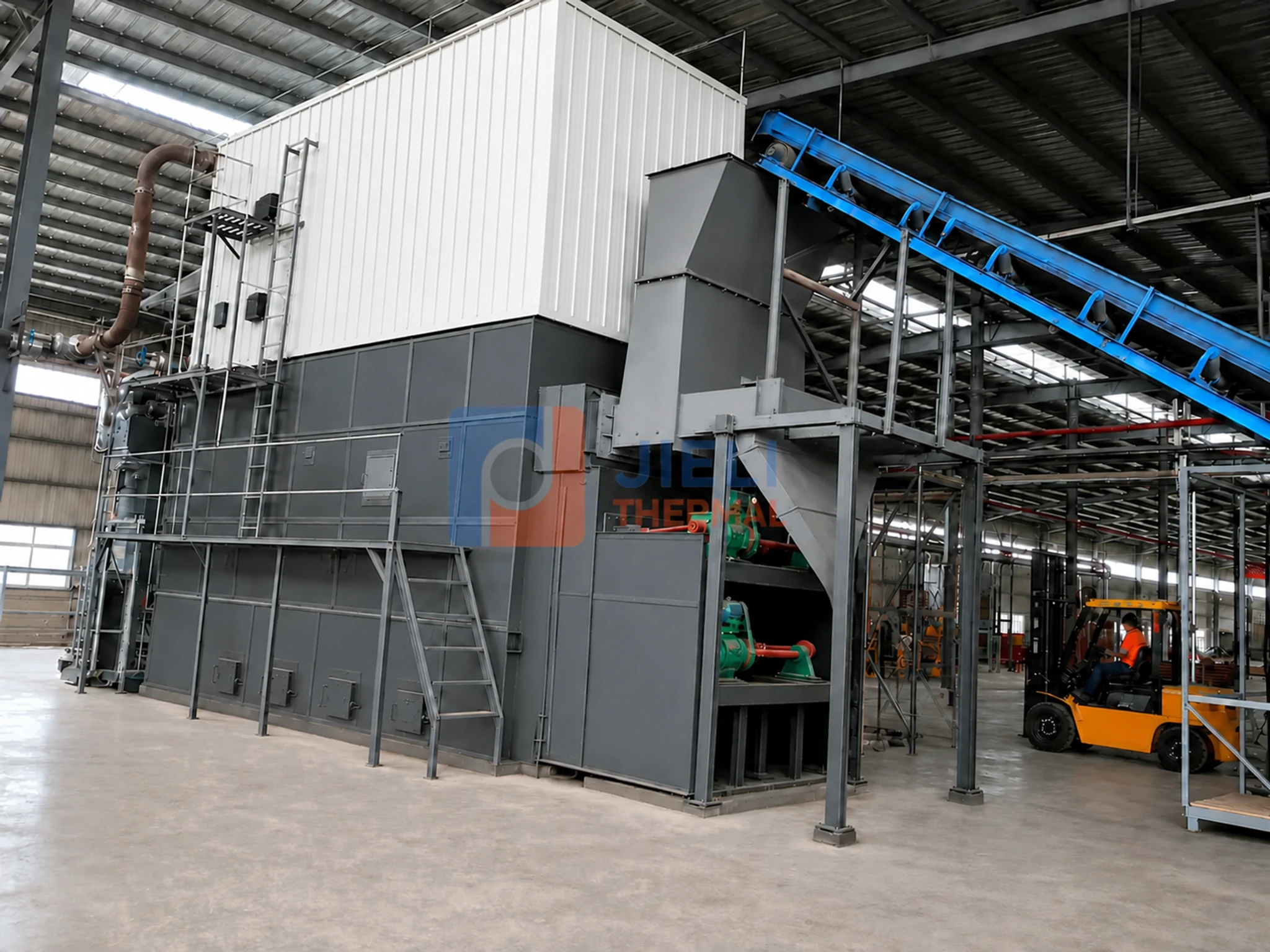
Thermal Oil Heater
Robust process-heating systems designed around biomass fuel characteristics and stable thermal-oil circulation.
View solution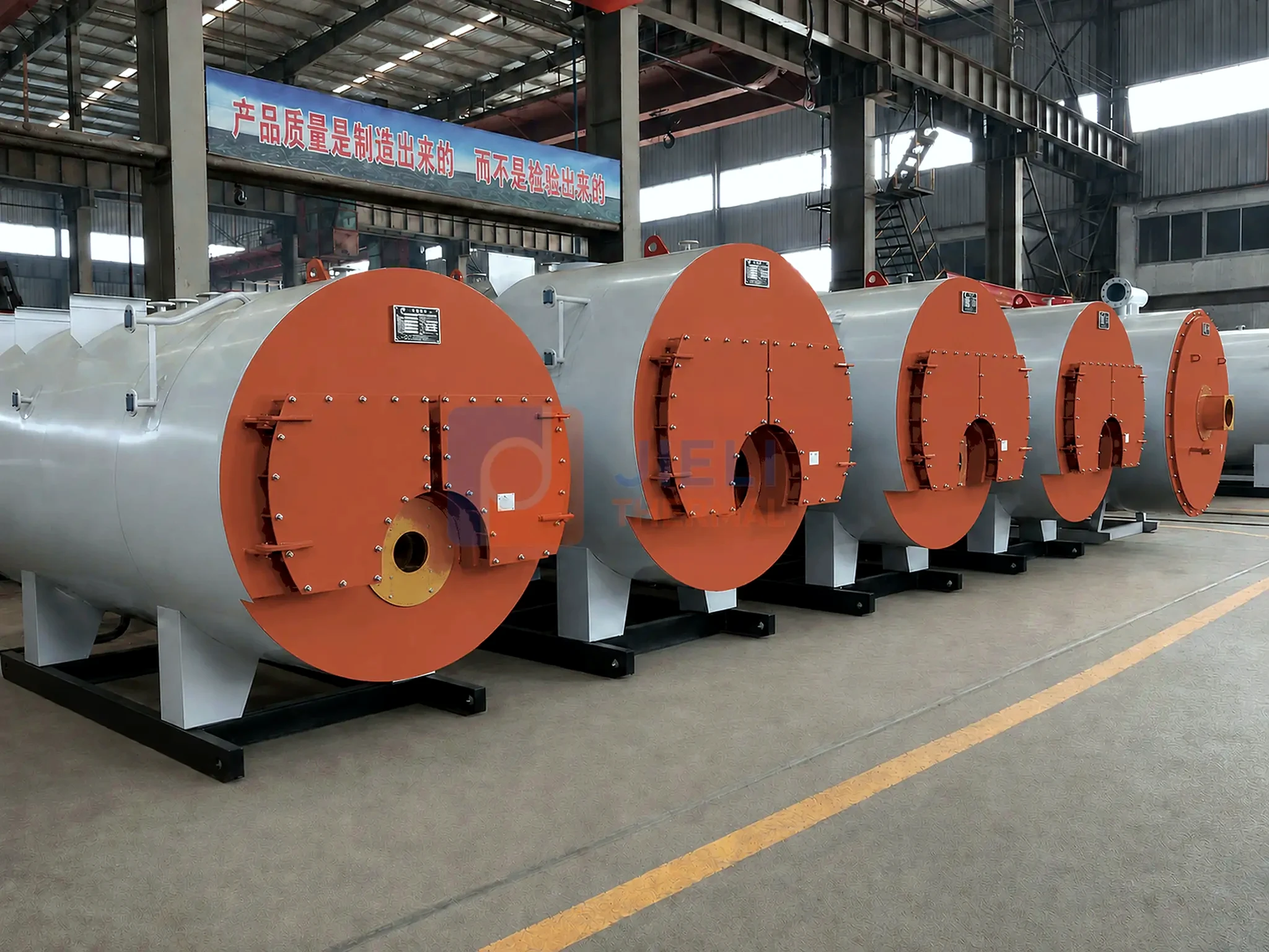 Priority solution
Steam Boiler
Industrial steam generation with compact integration, automated control and project-specific auxiliary systems.
View solution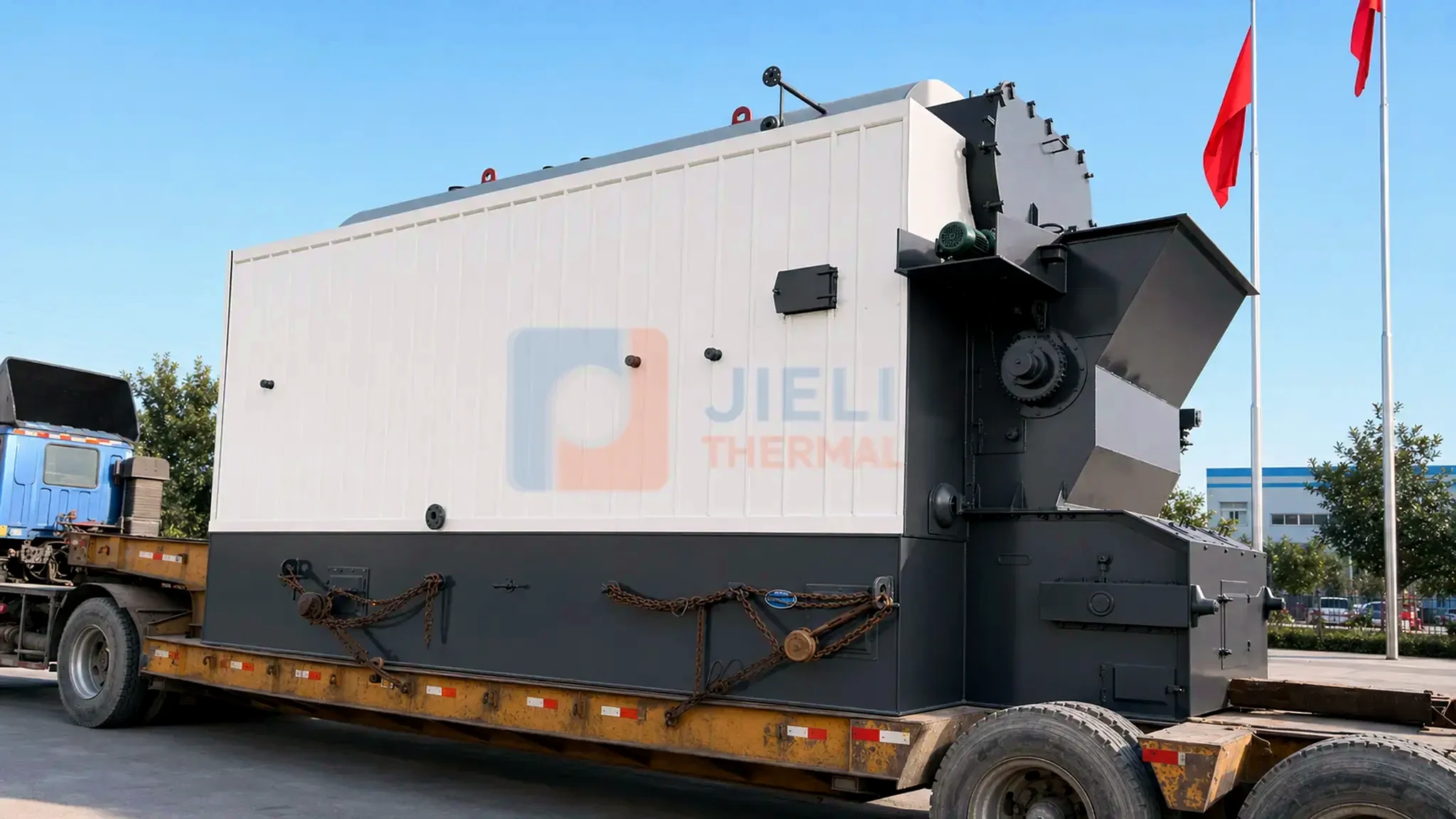
Steam Boiler
Fuel-adapted biomass steam systems for continuous industrial production and complete plant integration.
View solutionIndustry and engineering guides
These practical pages connect the heater to chemical-process duty, circulation hydraulics and fluid expansion. For large gas-fired duties, use the 2–12 million kcal/h thermal oil heater capacity guide as a screening reference. Final selection follows the confirmed fluid, layout, code and operating data.
Review reactors, distillation, drying, tanks, hazardous-area inputs and the complete supply boundary in the chemical industry thermal oil system guide.
Estimate preliminary flow and main-pipe diameter with the thermal oil flow and pipe-size calculator, then calculate hydraulic head and NPSH using the thermal oil pump guide.
Convert system charge and fluid expansion into a usable tank range with the expansion tank sizing guide.
Review the heat sink, dew point, fouling and fan margin in the economizer and air-preheater selection guide.
Build production-cycle and hydraulic inputs with the plywood hot-press thermal oil heater guide.
Plan startup and dehydration, then trend condition using the thermal oil testing guide.
Integrated package
For a coordinated heater, pump and fluid-handling package, see our skid-mounted gas and oil thermal fluid heater systems, including a presentation image, site photograph and supply-boundary checklist.
STARTUP & SYSTEM SUPPORT
JIELI’s original thermal oil boil-out notes explain pressure fluctuations, pump behavior and expansion-tank level. Review the staged observation example with your commissioning team and download the startup observation log.
Start a project
Start with approximate capacity, fuel, application and country; mark missing values as "not known yet". We can review the technical basis and supply options before preparing a project-specific quotation. Use the form, email or WhatsApp.