
JIELI ORIGINAL FIELD CASE ANALYSIS
Thermal Oil Heater Pump Pressure Fluctuations During Heat-Up
A 2,000,000 kcal/h gas-fired heater, intermittent pump noise, expansion tank vapor and a return to steady operation at 160°C.
A 2,000,000 kcal/h gas fired thermal oil heater had operated steadily at 120°C for years. When the process required a higher oil temperature, the circulation pump discharge pressure began to fluctuate. By about 125°C, the gauge was visibly swinging, the pump made intermittent abnormal noise, and vapor leaving the open expansion tank condensed into water droplets.
The system eventually ran steadily at 160°C after a slow heat-up lasting about two days, without replacing the pump or changing valve positions. Those observations shifted our investigation from pump sizing alone toward water vaporization, gas release and possible volatile components in the heat transfer fluid. The exact source of the water, and the composition of the released vapor, remained unconfirmed.
About this record: This article is based on JIELI THERMAL’s field case analysis. The temperatures and duration describe this particular event; they are not a recommended heat-up schedule or a general safe operating limit.
The thermal oil heater and the operating change
The customer needed to raise the thermal oil operating temperature from 120°C to 160°C after a change in the production process. The equipment was a gas-fired thermal oil boiler using mineral-based heat transfer oil; the heating medium remained liquid in normal service. According to the customer, the same oil had been in service for approximately two to three years and had not been replaced during that period.
| Item | Reported condition |
|---|---|
| Heater type | Gas-fired thermal oil heater |
| Thermal capacity | 2,000,000 kcal/h |
| Heat transfer fluid | Mineral-based thermal oil |
| Oil service history | Approximately 2–3 years; no oil replacement reported |
| Previous operating temperature | 120°C |
| Required operating temperature | 160°C |
| Circulation pump rated flow | 150 m³/h |
| Circulation pump rated head | 50 m |
| Reported cold-system pressure | Approximately 4 kgf/cm²; measurement location, pressure reference and pump operating state require confirmation |
| Expansion tank | Open tank, connected to atmosphere |
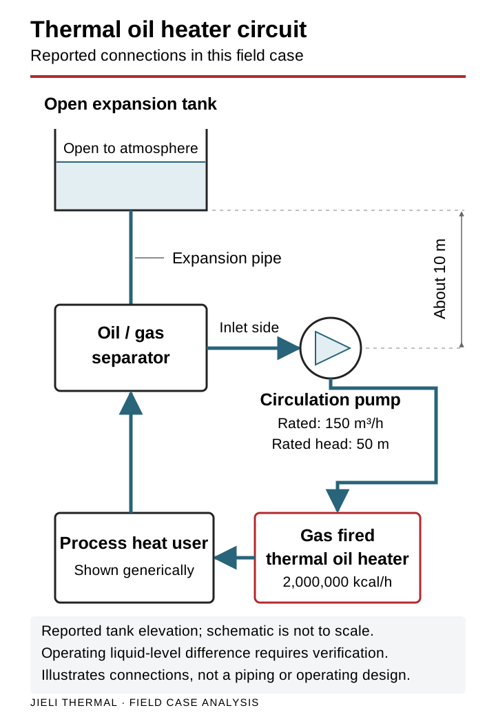
| Reported tank elevation | Approximately 10 m above the circulation pump |
| Expansion pipe connection | Top of the oil–gas separator |
| Oil–gas separator position | On the circulation pump inlet side |
The open expansion tank provided a static-head contribution through its connection to the separator. The separator and expansion pipe formed the route for gas release and fluid make-up. The reported tank installation height is not a measurement of the actual operating liquid-level difference. For the underlying arrangement, see our thermal oil expansion tank, deaerator and expansion pipe notes.
The 150 m³/h and 50 m figures are the pump’s rated values. They do not establish its actual operating flow or available suction margin in this installation.
What changed as the oil temperature rose
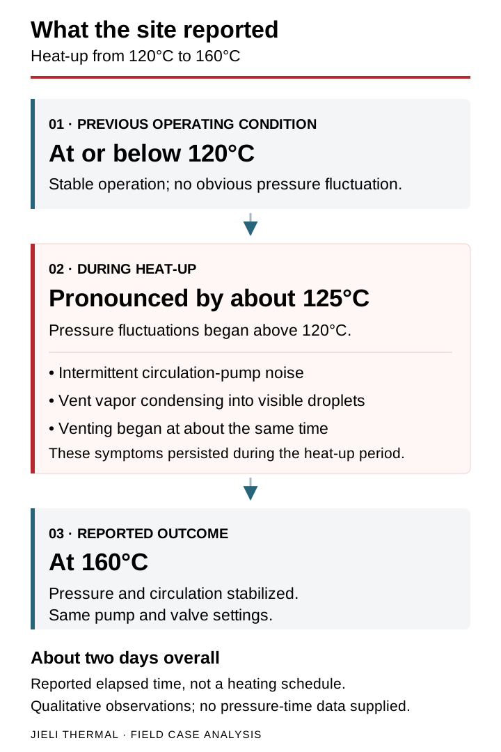
At 120°C and below, the customer reported stable operation. The circulation pump ran normally and its discharge pressure gauge showed no obvious fluctuation.
As the oil temperature rose above 120°C, the discharge pressure began to fluctuate. At approximately 125°C, the up-and-down movement of the gauge was clearly visible. The fluctuations persisted as heating continued.
Three accompanying observations mattered to the diagnosis:
- Intermittent pump noise. The abnormal sound came and went; it was not a continuous noise throughout operation.
- Vapor at the expansion tank. Vapor discharge from the top of the tank began at almost the same time as the pressure fluctuations. It condensed into visible water droplets in the cooler surroundings.
- A prolonged heat-up. The process took about two days. During this time, pressure fluctuations varied in severity while gas and vapor continued to leave the expansion tank.
The field record does not include a logged pressure trace, measured vapor composition or a measured flow curve. The relationship between temperature, venting and pump behavior therefore provides diagnostic evidence, rather than a complete measurement of the mechanism.
Why an oversized circulation pump was not the leading conclusion
Our initial concern was that the pump might be delivering too much flow against relatively low system resistance. At an unsuitable operating point, excessive flow can contribute to poor suction conditions and cavitation. The rated flow and head made that possibility worth checking, but they could not prove that the pump was oversized.
No valve was closed to throttle the flow. Other valves were not opened or closed to alter system resistance, and the circulation pump was not replaced or deliberately operated differently. With the same pump and valve arrangement, the thermal oil heating system eventually reached 160°C and ran steadily. The report describes stable circulation and a discharge pressure gauge that no longer fluctuated noticeably.
This outcome made persistent cavitation caused solely by excessive pump flow and insufficient system resistance a less convincing explanation for the event. It did not establish that the pump was operating at its optimum point, and it did not rule out temporary or local cavitation during heat-up. An assessment of the actual operating point still requires flow measurements, suction conditions and the pump curve, as explained in our thermal oil circulation pump selection guide.
Water vaporization and gas entrainment: the leading explanation
Visible vapor discharge, condensed water droplets, intermittent pump noise and pressure fluctuations appearing at almost the same time pointed toward a change in the circulating fluid’s condition. Water vaporization and gas entrainment were the first mechanisms we considered.
Water does not always boil at 100°C. Its saturation temperature depends on the local absolute pressure. The following approximate values help explain why water in one part of a thermal oil system may vaporize while conditions elsewhere appear stable.
| Absolute pressure | Water saturation temperature |
|---|---|
| 1.0 bar(a) | 99.6°C |
| 1.5 bar(a) | 111.3°C |
| 2.0 bar(a) | 120.2°C |
| 2.5 bar(a) | 127.4°C |
| 3.0 bar(a) | 133.5°C |
| 4.0 bar(a) | 143.6°C |
| 5.0 bar(a) | 151.8°C |
Here, bar(a) means absolute pressure. These values are for water, not the thermal oil’s boiling range, and they are not heat-up setpoints. A pump discharge gauge reading cannot be substituted for the pressure at another location in the circuit.
If water is present and the local temperature and pressure allow it to vaporize, the resulting vapor may reach the oil–gas separator. Some vapor or gas may then continue toward the pump inlet. Gas–liquid flow can interrupt a pump’s continuous liquid supply, vary its developed head and produce short-term changes in flow, discharge pressure and sound. That mechanism fits the reported observations, although the observations alone do not prove exactly where vapor formed or whether cavitation also occurred.
The source of the water was not established
The customer’s account of two to three years of operation at 120°C must be considered. With adequate circulation and effective venting, readily removable residual free water might be expected to leave the system earlier. Even so, the operating history does not show that every part of the circuit had been fully dehydrated. Local pressure, stagnant sections and possible later ingress still need investigation.
We could not simply attribute the condensate to water left from the original commissioning. The unresolved possibilities included:
- Water retained in poorly circulated or stagnant sections.
- Continuous or intermittent ingress during service.
- A small leak from water-side heat exchange equipment, if such equipment is connected.
- Rainwater or condensate entering the open expansion tank.
- Dissolved or dispersed water in the heat transfer oil.
These are possible routes to investigate, not defects confirmed in this installation.
Could low-boiling components in the thermal oil contribute?
The mineral-based heat transfer fluid had been used for approximately two to three years. Oxidation, thermal cracking and other changes in fluid composition are possible during service, depending on the conditions the oil has experienced. If low-boiling volatile components are present, a temperature increase may release them into the circulating system.
Such release could contribute to gas entrainment, a changing fluid condition at the pump inlet, and unstable gas–liquid pumping. It could therefore have played a part in the pressure fluctuations and intermittent noise.
No oil analysis was available for this case. Fluid age alone does not prove excessive degradation or severe thermal cracking, and we could not identify the vented vapor as low-boiling oil components. Water vaporization remained the priority suspicion; the contribution from volatile components remained unresolved.
What the expansion tank height tells us about pump suction
The reported arrangement placed the open expansion tank about 10 m above the circulation pump, with the expansion pipe connected to the top of a separator on the pump inlet side. That hydraulic connection can contribute static pressure and provide a path for gas release, provided it remains effective.
Using an assumed oil density of 850 kg/m³, a 10 m liquid column would contribute approximately 0.83 bar:
Δp = ρgΔz ≈ 850 × 9.81 × 10 = 83,385 Pa ≈ 0.83 bar
This is an illustrative static-head calculation from the report. The density was an estimate, and the reported tank height is not a verified minimum liquid-level elevation. Actual suction conditions also depend on atmospheric pressure, liquid level, fluid temperature and properties, and losses between the tank connection and pump inlet.
The calculation neither verifies the reported cold-system reading of approximately 4 kgf/cm² nor replaces a net positive suction head assessment. That pressure reading needs its measurement point, gauge or absolute reference, and pump operating state confirmed before it can be used in the analysis.
Available NPSH (NPSHa) must be checked against the pump’s required NPSH (NPSHr), with the margin specified for the equipment and duty. In a thermal fluid heater, a reasonable pump selection does not prevent gas–liquid flow when vapor or gas reaches the inlet. Local cavitation could not be excluded in this case, but the available evidence did not identify excessive flow alone as the main cause.
Our working diagnosis
| Possible mechanism | Assessment from the field record |
|---|---|
| Water vaporization | Leading suspicion. Vapor discharge during heat-up produced visible condensate; the water source was not identified. |
| Gas release and entrainment | Strongly supported as a working explanation by the timing of venting, noise and pressure fluctuations; the gas composition was not measured. |
| Release of low-boiling oil components | Could not be excluded. No fluid test results were available to confirm their presence or contribution. |
| Persistent cavitation caused by excessive pump flow | Not the leading suspicion. Steady operation at 160°C was eventually achieved without pump replacement or valve adjustment; actual flow still required verification. |
| Temporary or local cavitation at the pump inlet | Could not be excluded. Intermittent noise and pressure fluctuation are not sufficient to separate cavitation from other gas–liquid flow effects. |
Our conclusion was that the release of water vapor, gas or volatile components during heat-up was more likely to have disturbed the pump inlet fluid condition than a persistent pump-sizing mismatch alone. Water vaporization and gas entrainment deserved priority investigation. This remained a working diagnosis, not a laboratory-confirmed root cause.
Checks for a thermal oil heater with similar pressure fluctuations
Pressure fluctuation during thermal oil heater startup or a temperature increase should not automatically be treated as an oversized pump, insufficient system resistance, or normal dehydration. The first task is to distinguish inadequate hydraulic conditions from gas or vapor entering the circulating fluid.
Check the pump’s hydraulic conditions
Review the actual circulation flow, pump inlet pressure, NPSHa against NPSHr, suction-line and strainer condition, expansion tank level and elevation, and the expansion pipe connection. Establish whether the pump is operating within its appropriate range. A hydraulic problem must be corrected; forcing the temperature upward is not a remedy.
Check for water and volatile components
Look for abnormal expansion tank venting, vapor that forms condensate, intermittent pump noise, and a time relationship between temperature changes, venting and pressure fluctuation. Check the fluid for water, an abnormally low flash point or other signs of a change in condition. Investigate the source and establish acceptable pump inlet conditions, circulation flow and equipment condition before deciding how to proceed.
A small pressure fluctuation is not, by itself, permission to continue heating. The two-day duration in this case is an observation, not a boil-out or dehydration procedure for other systems. Our thermal oil heater startup, venting and dehydration guide provides related background; the applicable equipment and fluid procedures remain essential.
Record the measurements needed to distinguish the causes
- Pump inlet pressure: assess suction conditions at the relevant temperature.
- Pump discharge pressure: track stability alongside the inlet reading.
- Actual circulation flow: establish the operating point instead of relying on rated flow.
- Motor current: look for changes in pump load.
- Expansion tank level: track changes in fluid inventory and expansion.
- Expansion tank venting: record when gas or vapor release occurs.
- Oil water content: determine whether water is present in the sampled fluid.
- Oil flash point: provide supporting evidence of changes involving volatile components.
If marked pump vibration, cavitation-like noise, a drop in flow or severe pressure fluctuations occur, stop increasing the burner firing rate. Where necessary, shut down according to the equipment’s safety procedure. Blind throttling or continued forced heat-up can obscure the cause and compromise circulation.
Test the fluid and condensate
The report recommends Karl Fischer water analysis, flash point, kinematic viscosity and acid number testing. Gas chromatography may also be needed to examine low-boiling components. A sample of condensate from the expansion tank can help establish what is being discharged, using an appropriate safe sampling method. Our thermal oil testing and replacement guide explains the role of fluid-condition checks.
Outcome and remaining questions
The gas-fired thermal oil heater ultimately operated steadily at 160°C using the existing circulation pump and valve arrangement. The discharge gauge settled, and the pump’s operation stabilized. This showed that the disturbance was temporary under the reported conditions.
It did not prove that all water had been removed, establish the source of the moisture, confirm the composition of the vented vapor, or show that no local cavitation had occurred. Nor did it demonstrate a universal safe heating rate.
The practical lesson from this case is to read the pump, expansion tank and heat transfer fluid together. When pressure fluctuations coincide with vapor discharge and intermittent pump noise, investigate the fluid condition and pump suction conditions before assigning the fault to pump size or changing valve positions.
Technical references
The following references support the general fluid and pump principles discussed here. They do not independently verify the customer’s field observations or establish the cause of this incident.
- NIST: saturated-water properties, pressure table — background for the water saturation temperatures.
- Eastman heat transfer fluid technical guidance — background on moisture, low-boiling components and fluid condition.
- KSB: net positive suction head (NPSH) — definitions of available and required suction head.