

THERMAL OIL COMMISSIONING
Thermal Oil Heater Startup, Venting & Dehydration Guide
Commission in order: complete mechanical checks, charge clean oil, prove circulation, remove moisture, test protection and record the operating baseline.
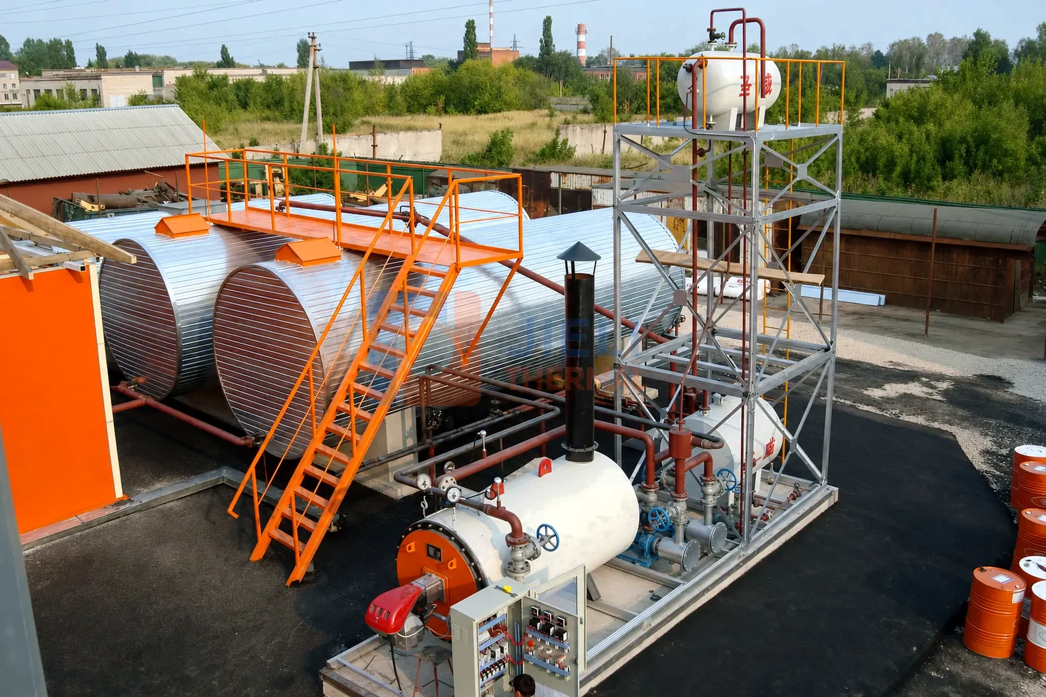
QUICK ANSWER
A thermal oil system should be mechanically complete, clean, circulating and demonstrably dry before normal-temperature operation.
Verify first
Confirm drawings, pressure testing, cleanliness, valve line-up, instruments, pump rotation and expansion capacity.
Heat gradually
Residual water and low-boiling material must leave through the designed route under the approved startup procedure.
Prove protection
Test flow permissives, temperature trips, fuel shutdown and power-failure response before production handover.
Use this checklist with the heater manual, fluid-supplier procedure and approved P&ID.
01 · APPROVED BASIS
Freeze the commissioning boundary before introducing thermal fluid.
Confirm the approved P&ID, manuals, cause-and-effect matrix, electrical drawings and valve list. Assign control of filling, pumps, heat input and venting before startup.
Record the fluid product, batch and condition. Confirm compatibility and removal requirements for any previous oil, cleaner or flushing fluid.
02 · MECHANICAL COMPLETION
Check cleanliness, drainage, expansion and pump suction conditions.
| System area | Pre-start evidence |
|---|---|
| Heater and piping | Completed inspection, pressure test, supports, insulation status and documented reinstatement |
| Low points and high points | Accessible drains and vents matching the approved P&ID |
| Pumps and strainers | Correct rotation, alignment, seal arrangement, clean suction path and temporary strainer plan |
| Expansion and storage | Usable expansion volume, level indication, fill/drain route and approved vent or inerting arrangement |
| Instruments and controls | Calibration, loop checks, setpoint authorization and power-failure state |
Remove construction debris. Monitor temporary strainer differential pressure and define when the strainer will be cleaned or removed.
03 · CHARGING AND COLD CIRCULATION
Fill through the designed connection and establish stable circulation before firing.
For approved cold filling with the heat source disabled and no residual heat requiring circulation, see the cold-filling pump cycling and air-venting guide. It explains priming checks, motor-start limits and when circulation must not be interrupted.
Use clean, dry transfer equipment and the specified fill connection. Monitor oil level, leaks and trapped air.
With the heater off, confirm rotation, suction conditions, differential pressure and flow through each circuit. Investigate cavitation, unstable level or loss of flow before firing.
04 · CONTROLLED DEHYDRATION
Water must leave through a safe, engineered route—not by rapidly increasing temperature.
Water left after testing, cleaning or process leakage can flash to steam and interrupt circulation. Use the fluid supplier’s controlled dehydration procedure.
Maintain circulation and the designed vapor-removal path. Monitor temperature, pressure, tank level and pump behavior. Set vent and blanketing valves according to the actual system procedure.
Set ramp rates and hold points for the selected oil, water content and venting capacity. If substantial water is suspected, obtain a removal plan before heating.
JIELI ORIGINAL TECHNICAL NOTES · UPDATED SEPTEMBER 21, 2026
Thermal oil boil-out: what pressure, pump noise and tank level can tell you
These notes are an English adaptation of JIELI's original Chinese technical paper, 煮油的知识和过程 (Thermal Oil Boil-out: Principles and Process). They explain the relationship between cold circulation, entrained air, residual water, pump suction and staged heating. In this context, thermal oil boil-out means controlled dehydration and degassing of a thermal-fluid system; it does not mean deliberately boiling the heat-transfer oil.
The practical focus is to read several signals together: circulation, pressure trend, pump sound, expansion-tank level and vent behavior. A quiet pressure gauge alone does not establish adequate flow or authorize firing.
1. Cold oil, entrained air and dispersed water
Cold thermal oil is generally more viscous than the same fluid at operating temperature. Where residual air or water is present, pump shear can disperse gas bubbles or water droplets through the oil. The source paper describes this mixed condition as “emulsification.” More precisely, entrained air forms a gas–liquid dispersion; water droplets dispersed in oil can form an oil–water emulsion. They are related startup problems, but they are not the same physical state, and neither is inevitable in a properly dried and vented system.
High cold-oil viscosity slows bubble separation. Controlled heating reduces viscosity and assists gas and moisture removal after circulation is established.
2. Why the cold pressure reading may be low
The source notes describe a pressure gauge changing from wide swings to a steadier, lower reading during cold circulation. Entrained gas can impair a centrifugal pump's delivery, while cold-fluid viscosity and suction losses also affect the operating point. A lower or steadier gauge reading is therefore an observation to investigate, not a universal pass criterion.
Compare pump suction and discharge pressure, differential pressure, measured or proved flow, motor current, tank level and the pump curve at the actual fluid temperature. Distinguish normal operating pressure from the equipment's design pressure: startup does not require the gauge to reach the design-pressure rating.
3. Heating and dehydration must be coordinated
The source paper emphasizes that circulation alone may not remove finely dispersed moisture. Heating changes viscosity and promotes moisture release, but water expanding into steam can interrupt flow or eject hot oil if heat input exceeds the system's ability to separate and remove vapor. The temperature measured in the bulk fluid can also differ from the temperature beside a heated surface.
Use the approved vapor-separation and collection route. An open expansion tank, a closed pressurized tank and a nitrogen-blanketed system require different arrangements; do not assume that vapor should discharge directly to the atmosphere.
4. Expansion-tank level supports reliable pump suction
In an elevated-tank arrangement, the liquid column helps establish static head at the pump suction. The source paper highlights what happens when the level falls far enough to admit air or lose this liquid connection: circulation can become unstable and the pump can lose prime. Static head, suction-pipe losses and vapor pressure must be considered together.
Low level, loss of flow, violent pressure fluctuations or metallic pump noise are abnormal conditions. Stop heat input and follow the approved safe-shutdown and pump-protection sequence. Do not keep firing through severe cavitation, run an unfilled pump or add water to the oil system.
SOURCE EXAMPLE · OBSERVATION POINTS
A 280°C thermal oil system: staged dehydration observations
The following temperature points come from JIELI's original notes for a system intended to operate at 280°C. They are an example for engineering review, not universal setpoints or a standalone operating procedure. Select the actual ramp, hold points and release criteria from the installed equipment, fluid supplier's instructions, moisture condition and approved commissioning plan.
| Source temperature point | What the notes highlight | How to assess the condition |
|---|---|---|
| Cold circulation, before the approach to 90°C | Establish continuous oil circulation before introducing heat. The source groups this with the initial approach to 90°C. | The system and pump must already be filled with oil. Circulate with the heater off first; do not interpret “dry circulation” as running the pump dry. Prove the required flow and firing permissives before controlled heating begins. |
| Around 95°C | An early observation point for thermal inertia, initial vapor release and pressure changes. | A heated surface may be hotter than the bulk reading. The responsible commissioning team controls heat input under the approved plan. Vapor or smoke is not automatically evidence of successful moisture removal. |
| Approximately 105–130°C | The source describes a main moisture-release stage, with a risk of surging and expansion-tank overflow. | Monitor flow, level, pressure and the designed vapor-removal route. Severe cavitation, violent gauge movement or loss of circulation require heat shutdown and investigation; they are not acceptable targets to maintain. |
| Around 130°C | A checkpoint for restored stable circulation and reduced vapor release. | Stable flow, normal pump behavior, appropriate operating pressures and the approved moisture-release criteria must agree. Reaching 130°C does not prove that every part of the system is dry. |
| Approximately 130–210°C | The source proposes a subsequent rise of 10–20°C per hour after dehydration is verified. | This is the source example's ramp range, subject to fluid and equipment approval. Change temporary vent valve positions only under the approved P&ID and procedure; keep all required expansion, relief and safety paths available. |
| Approximately 210–230°C | A second observation stage; the source suggests a 1–2 hour hold if the fluid behavior requires it. | Investigate any renewed gas evolution with the fluid supplier. Its composition cannot be identified from temperature alone, and this range is not a universal boiling threshold for “heavy components.” |
| 280°C in this example | The intended operating condition and transition to controlled process loading. | Proceed only within the approved bulk and film-temperature limits, with circulation and safeguards proved. Record supply/return temperature, flow, pressure drop and tank level; 280°C is not the operating target for every thermal oil system. |
What “dehydration complete” means: meet the written acceptance criteria for the whole circuit, including remote branches and process users. Temperature and visible venting alone cannot exclude trapped water. If significant water contamination is suspected, obtain specialist instructions before further heating.
Record the evidence at each startup hold point
A useful commissioning record connects the time and fluid temperature to suction/discharge pressure, flow proof, pump current, tank level, vent observations and the person authorizing the next stage. Keep the readings with the approved P&ID, fluid data sheet and protection-test results.
Download the blank thermal oil startup observation log (CSV) · Download these English technical notes (PDF)
For system selection, see the thermal oil heater range. For related design checks, review expansion-tank sizing, circulation-pump selection and thermal oil flow and pipe sizing.
05 · HOT COMMISSIONING
Raise temperature in controlled stages and inspect the complete loop.
After dehydration is complete, continue staged heating while monitoring supply and return temperatures, heater differential pressure, pump current, expansion level, leakage, supports, unusual vibration and process-user response. Recheck flange joints and equipment only under the approved hot-work and isolation method; high-temperature fluid can remain hazardous after firing stops.
Confirm control stability at minimum and normal production load. Check branch balancing, standby-pump transfer, burner or fuel-system turndown, expansion behavior and the relationship between process demand and heater outlet temperature. Record the operating baseline for later troubleshooting.
06 · SAFEGUARDS
Test the approved cause-and-effect matrix with recorded results.
Typical project checks may include loss of circulation, low flow or differential pressure, high outlet temperature, expansion-tank level, pump trip, flame or fuel failure, fan or draft failure where applicable, emergency stop and power loss. The exact devices, setpoints, voting and shutdown sequence are project-specific.
Testing should verify both the initiating signal and the final safe response. Simulating a screen indication without proving the fuel shutoff or controlled equipment state is not a complete functional test.
Commissioning handover record
- Approved as-built P&ID, equipment and electrical drawings;
- Fluid product, batch, charged quantity and initial sample result;
- Pressure-test, flushing, cleanliness and strainer records;
- Instrument calibration, setpoints and cause-and-effect test sheets;
- Cold-circulation, dehydration and staged-heating log;
- Normal flow, temperatures, pressure drop, pump current and expansion level;
- Operator training, PPE, emergency response and maintenance instructions;
- Open punch items, spare parts and agreed performance-test status.
TECHNICAL REFERENCES
Fluid-supplier and system-engineering resources.
- Eastman Therminol — Technical resources for system startup and maintenance
- Eastman Therminol — Heat-transfer-fluid maintenance and sampling
- JIELI — Industrial boiler installation and commissioning checklist
- JIELI — Conceptual thermal oil system P&ID
The project manuals, approved P&ID, fluid supplier procedure and local safety requirements take precedence over this general guide.
FREQUENTLY ASKED QUESTIONS
Thermal oil startup and dehydration FAQ
Why must a thermal oil system be dehydrated before normal operation?
Residual water can form steam when heated, causing unstable pressure, pump cavitation, disturbed circulation and hazardous fluid discharge. Removal must follow the approved fluid-supplier and heater-manufacturer procedure.
Can a thermal oil heater be fired before circulation is established?
Normal firing should be prevented until the approved circulation permissive is satisfied. The exact flow proof, sequence and exceptions are defined by the project cause-and-effect matrix.
How fast should a new thermal oil system be heated?
There is no universal ramp rate. Fluid chemistry, system volume, residual moisture, vent design and equipment manuals determine the supervised heating stages and hold points.
When should nitrogen blanketing begin during startup?
Only according to the approved system and fluid-supplier procedure, after the required moisture and low-boiling removal path has completed its function. Closing or inerting the wrong vent path too early can obstruct dehydration.
Understanding the boil-out example
Does reaching 130°C prove that a thermal oil system is dry?
No. This temperature is an observation point in JIELI’s 280°C example, not a universal dehydration threshold. Confirm stable circulation and the approved moisture-removal acceptance criteria throughout the complete circuit.
Is thermal oil boil-out the same as boiling the oil?
No. The term refers here to controlled removal of water and entrained or evolved gas. The heat-transfer fluid must remain within its specified operating limits.
JIELI THERMAL ENGINEERING
Commission the thermal-oil loop as one operating system.
Send the P&ID, heater, fluid, system volume, process users, site scope and local approval route. JIELI can align equipment documentation and commissioning support with the contracted responsibility matrix.
Request a startup scope review