
JIELI ORIGINAL ENGINEERING NOTES
Thermal Oil Expansion Tank, Deaerator & Expansion Pipe
How three connected components support expansion, pump suction and gas release in a thermal oil heating system.
In a thermal oil heating system, the expansion tank receives the oil’s thermal expansion and provides static head; the oil–gas separator helps free gas leave the circulating liquid; the expansion pipe connects these functions. Their elevations and connections must be reviewed together with the circulation pump, not selected as three unrelated accessories.
This guide explains the elevated expansion arrangement described in JIELI’s original engineering notes. For vessel capacity, use the separate thermal oil expansion tank sizing guide and calculator.
Read the complete thermal oil system first
The NX-GR-L1200 process diagram shows the heater, return header, oil–gas separator, circulation pumps, expansion tank, storage tank and auxiliary lines. The English edition retains the supplied drawing’s connections, valve symbols, instrument tags and numerical annotations. Its pipe sizes and vessel capacities belong to this project; they are not a standard selection for every heater.
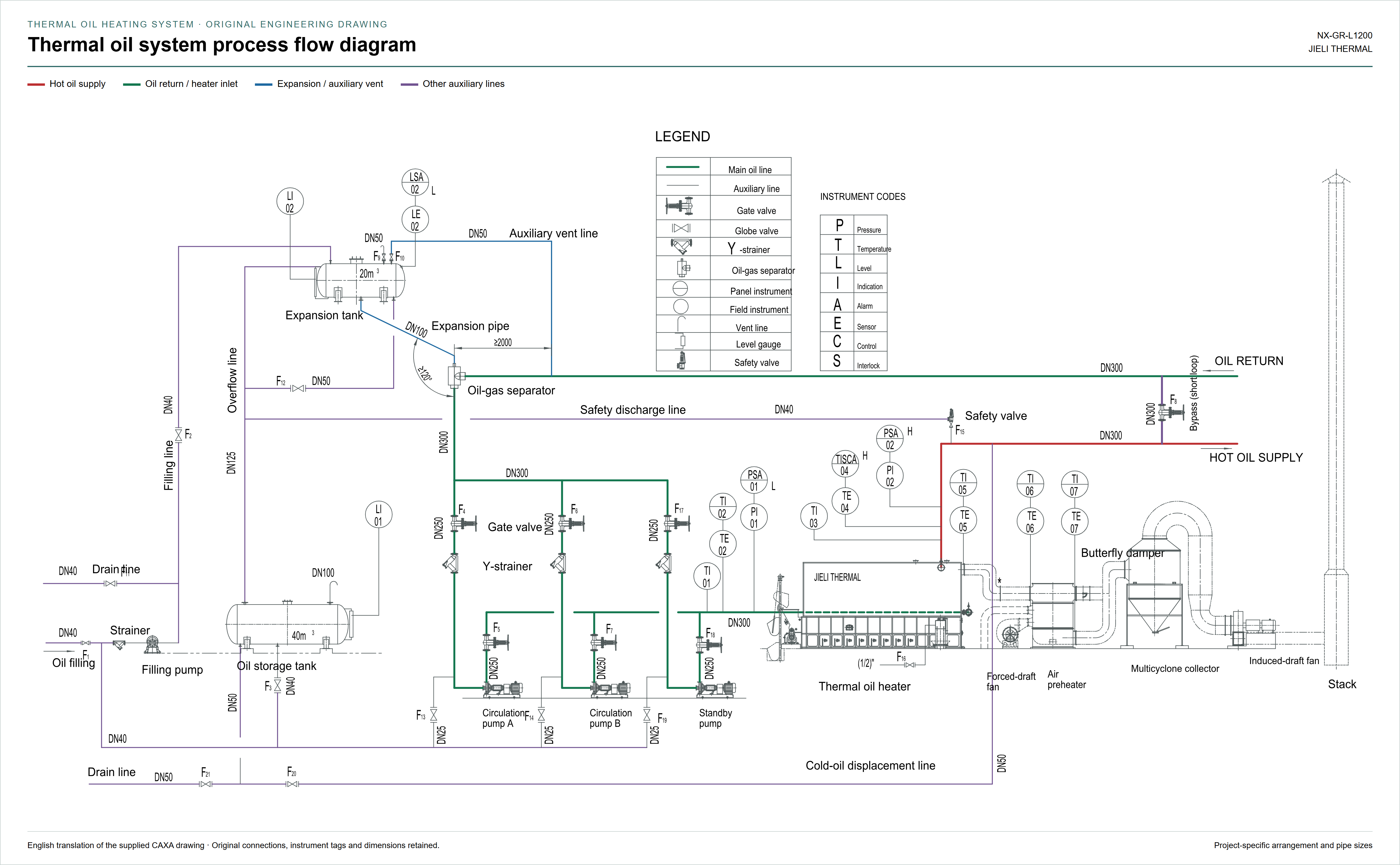
Follow the green return route through the separator and pump circuit toward the heater. The red route carries hot oil from the heater to the process. Blue identifies the expansion and auxiliary vent connections; purple distinguishes the other auxiliary lines. The colour key supplements the existing symbols and labels.
Expansion tank: working volume and static head
Oil expands as its temperature rises. The tank needs a defined cold level, hot level and gas space so expansion does not overfill it. Its elevation also helps keep the pump suction flooded. The volume calculation and the elevation check answer different questions: a sufficiently large tank can still be installed at an unsuitable height.
For the elevated arrangement in these engineering notes, JIELI uses at least 1.5 m above the highest connected piping or equipment as a layout criterion for the expansion tank. Specify the elevation datum on the project drawing. Calculate available static head from the minimum operating liquid level, not from the top of the vessel or its support frame.
This 1.5 m criterion is not a universal substitute for pump-suction calculations. Confirm fluid density and vapour pressure at the relevant temperatures, suction-line losses, tank gas-space pressure and the pump’s required NPSH margin. A sealed or nitrogen-blanketed arrangement must also account for its regulated pressure and relief design.
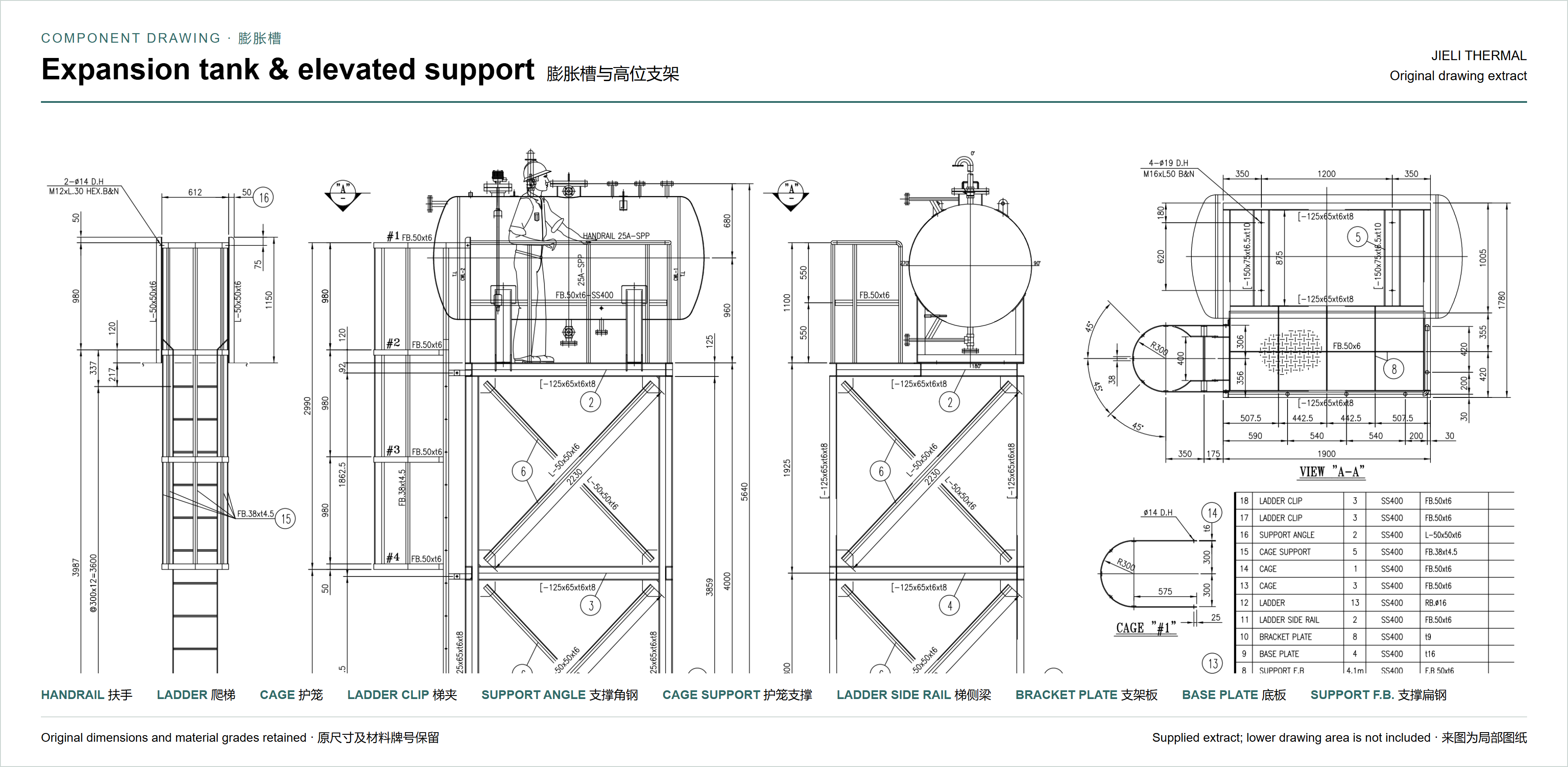
Eastman’s expansion-tank guidance also identifies thermal expansion, venting and positive pump-inlet head as connected functions. Tank temperature and exposure to air matter because hot organic heat-transfer fluid can oxidise. The final arrangement must match the selected fluid and system design. Source: Eastman expansion-tank design bulletin.
Oil–gas separator: a gas-release point and pressure reference
The vessel shown here receives oil through its side inlet, releases separated free gas upward through the expansion connection and returns liquid through its lower outlet. “Deaeration” here refers to removing entrained free gas from the thermal oil loop; it does not mean that all dissolved gas or moisture has been removed.
When the separator has an open hydraulic connection to the expansion tank, that connection provides the system’s pressure reference. At rest, the pressure difference is approximately ρgΔz, added to the pressure above the tank’s liquid surface. During circulation, local losses and the position of the connection also matter. The separator does not independently regulate pressure merely because it is called a pressure-reference point.

Place this gas-release point high in the connected circuit where the layout allows, while keeping the expansion tank above it and checking the pump suction arrangement. If another branch or item of equipment is higher, the main separator alone cannot guarantee that trapped air from that location will reach it.
Give difficult high points their own venting route
A high-point collection vessel or an auxiliary vent connection can provide a route from a gas pocket to the expansion tank’s gas space. Review elevated process equipment, inverted loops and local peaks individually. A vent connection is only useful if the actual pipe route allows gas to reach it.
Where auxiliary vent valves are included, identify their purpose and operating position on the approved drawing and commissioning procedure. An auxiliary vent valve is not permission to isolate the system’s required expansion or pressure-relief path. Vent discharge, overflow and any collected oil must be routed to the containment or safe destination specified by the design.
Expansion pipe: maintain a continuous rise
The expansion pipe should rise continuously from the separator toward the tank, without a downward pocket that can retain gas or liquid and obstruct communication. JIELI’s engineering notes favour a pronounced upward run, using 15–30° upward inclination as a layout reference where practicable. This is a project-design preference, not a universal code minimum.
Confirm the actual slope, internal diameter, support arrangement and thermal movement on the piping drawing. A steep section does not compensate for a later dip, a blocked connection or an incorrectly isolated line. The original diagram’s angle and distance annotations must be read against their own dimension lines, not reinterpreted as generic installation rules.
What to check before approving the arrangement
- Minimum tank liquid level relative to the pump inlet and the highest connected equipment.
- Usable expansion volume at the specified cold and hot temperatures.
- An unobstructed expansion connection and a continuous rising route.
- Venting provisions at local high points outside the main separator’s effective path.
- Defined auxiliary-valve positions, level protection and safe discharge destinations.
- Access for inspection, filling, drainage and maintenance.
These checks belong in the same review as thermal oil circulation-pump selection and the startup, venting and dehydration plan. Cold venting and heated dehydration are different operating stages.