


INDUSTRIAL THERMAL FLUID ENGINEERING
How to Select a Thermal Oil Heater: Temperature, Flow, Fuel and Complete-System Design
Select a thermal oil heater from heat duty and temperature, then match the fluid, circulation, expansion system, fuel and controls.
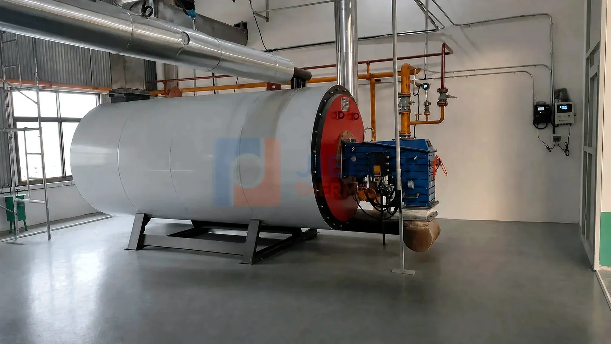
THE SHORT ANSWER
Select the heater and circulation loop together.
Define the thermal duty
- Normal, minimum and peak heat load;
- Required supply and return temperatures;
- Process heat exchangers and operating schedule.
Protect the heat-transfer fluid
- Respect bulk and film-temperature limits;
- Maintain dependable circulation through the coil;
- Control expansion, venting and oxidation exposure.
Confirm the fluid limits and installation requirements. Compare the JIELI thermal oil heater range and published specifications.
01 · HEAT DUTY & TEMPERATURE
Calculate what every process user needs.
Calculate each user’s normal and startup duty. Total the users that operate together. Select the thermal oil heater for this load profile, including minimum demand.
Set process, supply and return temperatures and the required control band. Allow for piping losses and heat-exchanger approach temperature.
02 · HEAT-TRANSFER FLUID
Use the fluid supplier's operating limits.
Check maximum bulk and film temperatures, cold-start viscosity, oxidation stability and compatibility. Evaluate the fluid over the full startup and operating range.
Bulk temperature is the main fluid-stream temperature; film temperature is the hotter layer at the heating surface. Excess film temperature can cause cracking and deposits. Coil heat flux and circulation therefore have to be evaluated together.
03 · CIRCULATION
Maintain reliable flow through every operating condition.
Calculate resistance through the coil, piping, valves, strainers and users. In a filled closed loop, rising and falling static heads balance; elevation still affects suction pressure and NPSH. Balance parallel branches.
Prove circulation before firing and trip heat input on low flow. Define standby pumping and residual-heat removal for the selected furnace.
04 · EXPANSION & VENTING
Allow the fluid to expand without exposing it unnecessarily.
Size the tank from total oil inventory and temperature-dependent expansion. Its elevation and connection also affect venting and pump suction pressure.
Keep tank temperature within the fluid supplier’s limits. Specify blanketing, pressure control, relief, overflow and drainage as one arrangement.
05 · FUEL & COMBUSTION
Choose combustion equipment for the available fuel.
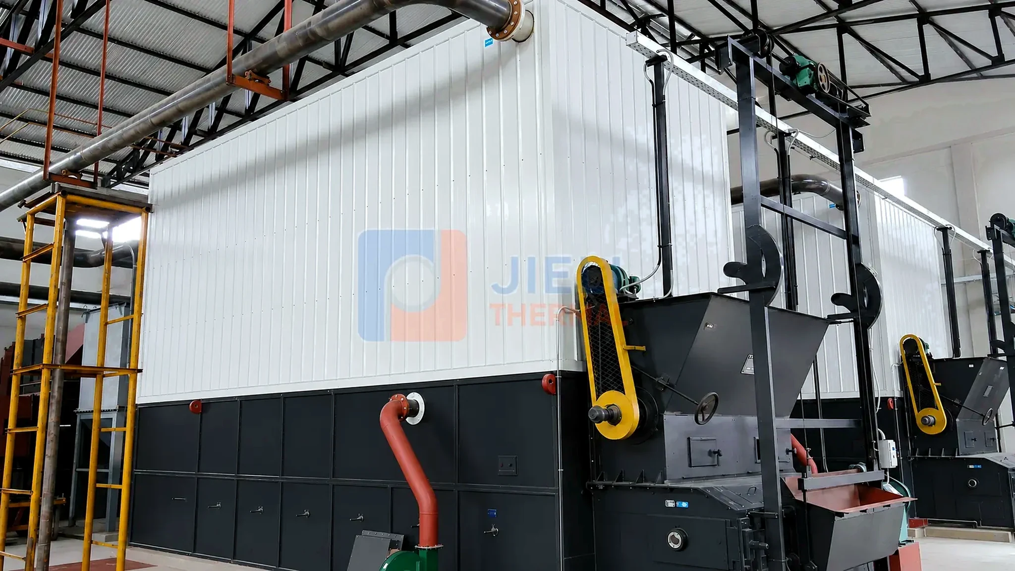
For gas or oil, confirm supply pressure, composition and burner turndown. For solid fuel, obtain moisture, ash, particle size, bulk density and heating value before selecting the furnace and feeding equipment.
For heat recovery, check the usable heat sink, cold-end corrosion, fouling and added draft loss.
06 · CONTROLS & PROTECTION
Design interlocks around credible failure modes.
Typical protection inputs include circulation flow, pump status, heater inlet and outlet temperatures, pressure, expansion-tank level, flue-gas temperature, flame or combustion condition, furnace draft and fan status. Alarm limits, trips, start permissives and restart requirements should be documented.
The operator interface should show process values, actuator states and the first-out cause of a shutdown. Good automation does not remove the need for operating procedures, inspections, fluid analysis and preventive maintenance; it makes those tasks clearer and more consistent.
07 · PROJECT INPUTS
Prepare these data before requesting a proposal.
- Normal, minimum, peak and start-up heat duty;
- Required supply, return and process temperatures;
- Process users, heat exchangers and operating schedule;
- Selected thermal fluid and supplier limits;
- Piping distance, elevation and proposed equipment layout;
- Fuel properties, supply conditions and emissions limits;
- Ambient range, altitude and available utilities;
- Required code, inspection and documentation scope;
- Redundancy, automation and future expansion expectations.
SYSTEM WORKING PRINCIPLE
Follow the complete heat-transfer loop, not the heater alone.
A thermal oil heater transfers energy through a continuously circulating liquid loop. Every step influences temperature control, fluid life and safe operation.
Heater
Fuel or electricity raises the thermal-fluid temperature inside the heating surface.
Circulation pump
The pump maintains the design flow needed to remove heat and protect the coil.
Process users
Reactors, dryers, presses, tanks or exchangers receive controlled indirect heat.
Return line
Cooled fluid returns through the closed loop for reheating.
Expansion system
The tank accommodates fluid expansion and supports venting and pump suction conditions.
HEAT-DUTY BASIS
Use one heat duty in several buyer-friendly units.
International projects may specify capacity in kW, MW, kcal/h or MMBtu/h. Unit conversion helps buyers compare models, but it does not replace a process heat balance.
Useful conversion: 1 MW = 1,000 kW = approximately 860,000 kcal/h = approximately 3.412 MMBtu/h.
Process duty
For steady flow, Q̇ = ṁ × cp × ΔT. With kg/s and kJ/kg·K, Q̇ is in kW. For batch heating, energy is m × cp × ΔT; divide by heating time to obtain average duty.
Warm-up duty
Include the mass of the product, vessel, piping and circulating fluid when start-up time matters.
Simultaneous load
Identify which users run together instead of simply adding every installed consumer.
System allowance
Review piping loss, operating margin and heat recovery separately; avoid unexplained oversizing.
SYSTEM SUPPLY BOUNDARY
Define what belongs inside the proposal.
A quotation is easier to compare when the equipment boundary is explicit. The following items are project-review categories, not a claim that every item is included by default.
Heater package
Heater body, burner or combustion equipment, insulation and local instruments.
Circulation loop
Operating and standby pumps, strainers, valves, bypasses and branch balancing.
Fluid management
Expansion, drain and filling arrangements, venting and optional inert-gas blanketing.
Controls and safety
PLC/HMI, flow permissives, temperature and pressure protection, alarms and first-out trips.
Heat and flue-gas recovery
Economizer or air preheater only after temperature, fouling, corrosion and draft are checked.
Project services
Documentation, inspection, packing, supervision, commissioning, training and spare parts as agreed.
LIFECYCLE RELIABILITY
Protect fluid life after commissioning.
Long-term reliability depends on operating discipline as much as equipment selection. Site procedures should be based on the selected fluid, heater design and local requirements.
- Confirm circulation before enabling heat input and investigate every low-flow trip.
- Trend supply, return, flue-gas and pump operating data instead of relying on one temperature reading.
- Sample the thermal fluid at an agreed interval and review viscosity, acidity, flash point and insoluble material with the fluid supplier.
- Inspect strainers, seals, valves, expansion-tank level, insulation and evidence of leakage or oxidation exposure.
- Document safe start-up, shutdown, emergency cooling and restart rules for operators.
PROJECT DOWNLOADS
Turn the guide into a project-ready inquiry.
The fillable checklist organizes the same inputs used in this guide. Complete what is known and leave uncertain items for technical clarification.
ENGINEERING REFERENCES
Further technical reading.
FREQUENTLY ASKED QUESTIONS
Thermal oil heater selection FAQ
What information is needed to size a thermal oil heater?
Provide normal and peak heat duty, supply and return temperatures, process users, operating schedule, thermal-fluid type, fuel, site altitude, ambient conditions, piping distance, required code and emissions limits. The circulation loop and process heat exchangers must be evaluated with the heater.
Is a thermal oil heater the same as a steam boiler?
No. A thermal oil heater normally circulates a liquid heat-transfer fluid for indirect heating, while a steam boiler generates steam. The process medium, temperature, pressure, distribution, controls and maintenance requirements are different.
Why is minimum flow important in a thermal oil heater?
Adequate circulation removes heat from the coil and helps control tube-wall and fluid-film temperature. Low flow can create local overheating, accelerate fluid degradation and damage equipment, so flow protection is a central design requirement.
How is the thermal oil expansion tank selected?
It must accommodate fluid expansion across the operating range and support filling, venting, pump head and safe system operation. Fluid properties, total inventory, elevation, temperature, inert-gas requirements and applicable standards must be reviewed together.
Can a thermal oil heater use biomass or coal?
Yes, where fuel economics and site conditions support a coal-fired thermal oil heater or another solid-fuel system. The complete project must include matched fuel preparation and feeding, furnace and grate design, combustion air, draft control, ash handling, emissions equipment and automatic protection.
COMPONENT CALCULATIONS
Continue from heater duty to circulation and expansion.
After confirming heat duty, temperature and fluid, use the thermal oil circulation pump selection guide to prepare the flow and hydraulic model. Then use the expansion tank sizing guide to estimate fluid growth and the tank's usable operating range. Both selections require final project engineering.