


THERMAL OIL HEATER DESIGN
Double-Coil Spacing in Gas-Fired Thermal Oil Heaters: Balancing Efficiency and Flue-Gas Resistance
In JIELI’s clean-gas double-coil designs, a radial clear gap below 50 mm is an experience-based starting point. Final spacing depends on heat transfer, gas resistance, hot clearances and manufacturing tolerances.
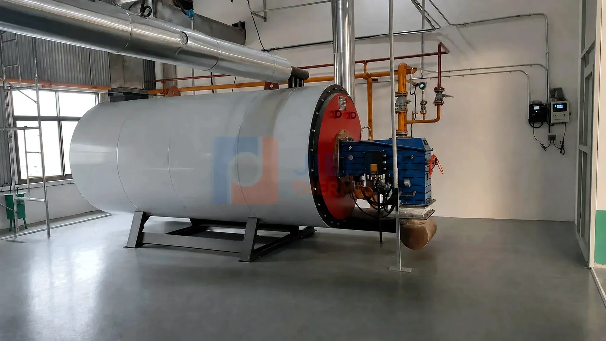
THE ENGINEERING ANSWER
Under 50 mm can be practical—but it is not a universal rule.
JIELI design practice
- For suitable clean natural-gas-fired double-coil heaters, we commonly evaluate a radial clear gap below 50 mm;
- The compact passage can improve gas-side convection and reduce bypass;
- The exact value is selected for the real heat duty and flue-gas flow.
Mandatory validation
- Maximum gas velocity and section pressure drop;
- Fan curve, furnace draft and operating turndown;
- Tube-wall/film temperature, expansion, tolerances and inspection access.
The 50 mm value is JIELI design experience, not a mandatory standard. Confirm it for the actual tube diameter, fuel and coil layout.
01 · DEFINE THE GEOMETRY
“Coil spacing” must name the correct dimension.
A double-helical-coil heater has concentric inner and outer coils. The furnace, inter-coil passage and outer gas passage must be assessed together.
Here, radial clear gap means the distance between facing tube surfaces of the inner and outer coils. It is different from the axial center-to-center pitch between turns of one helix.
| Design term | What it means | Why it matters |
|---|---|---|
| Radial clear gap, gr | Shortest clear distance between the facing surfaces of the inner and outer coil layers. | Controls annular free-flow area, gas velocity, convection and draft loss. |
| Axial turn pitch, pa | Center-to-center distance between adjacent turns in the same helix. | Affects the local gas path, exposed area, support detail and manufacturing. |
| Tube outside diameter, Do | Outside diameter of the pressure-part tube. | Changes surface area, blockage ratio, bending radius and oil-side flow area. |
| Concentricity | Alignment of the inner and outer coil axes along the heater. | Prevents one side becoming too tight while the opposite side becomes a bypass path. |
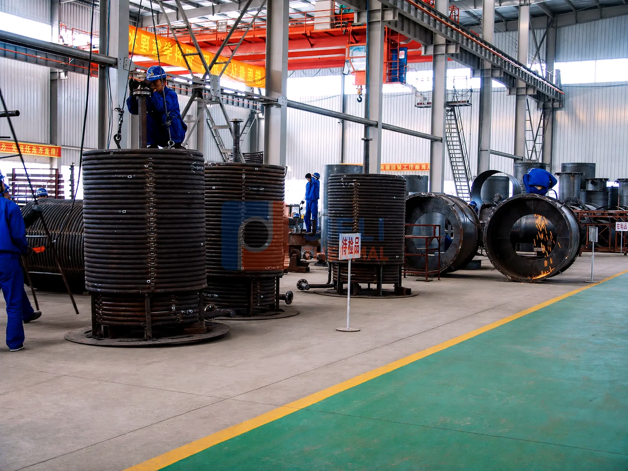
02 · GAS-SIDE HEAT TRANSFER
A smaller free-flow area increases local flue-gas velocity.
At fixed local gas volume flow, vg = V̇g / Afree. Reducing free area increases velocity. Recalculate Reynolds number using the new hydraulic diameter and gas properties; it does not necessarily rise in proportion to velocity.
Compare heat-transfer gain with draft loss at rated and minimum firing. Tube size, turn pitch, gas properties and flow distribution all affect the result.
For the convective section, Q = U · A · ΔTlm expresses the heat-transfer balance. Calculate furnace radiation separately. Spacing does not replace adequate surface area or oil circulation.
03 · FLUE-GAS RESISTANCE
The same acceleration that helps convection also costs draft pressure.
A useful loss relation is Δp ≈ K · ρv²/2. When the gap changes, both velocity and the geometry-dependent loss coefficient K may change. Recalculate contractions, turns and passage friction.
Combine coil losses with the air path, furnace, recovery equipment, ducts and stack. Check the fan curve at operating gas conditions. Fan shaft power is approximately Δptotal · V̇ / ηfan; electrical input also includes motor and drive losses.
Excess resistance can limit firing rate and furnace-pressure control while increasing fan power. Retain margin for the expected deposit condition.
04 · THE UNDER-50-MM WINDOW
Why it often works for clean gas—and why it still needs calculation.
For suitable clean natural-gas service, JIELI uses a radial clear gap below 50 mm as a design starting range. This is confirmed company experience, not a universal optimum.
It is accepted only after the calculated velocity, Reynolds number, heat-transfer duty and section pressure drop agree with the burner/fan arrangement. The check must include maximum firing, minimum stable load, cold start, expected excess air, site altitude and any downstream heat-recovery equipment. A 45 mm gap can be appropriate in one heater and unacceptable in another with a different tube diameter, capacity or gas-flow path.
Relative spacing also matters. For facing tubes of equal OD, S/D = (D + g)/D. A 50 mm gap gives about 2.32, 1.98, 1.83 and 1.66 for ODs of 38, 51, 60.3 and 76.1 mm. This simplified ratio is not a heat-transfer correlation for the full helical geometry.
| Operating case | How to treat the spacing | Main verification |
|---|---|---|
| Clean natural gas, stable load | An under-50-mm radial gap may be a practical starting point. | Rated velocity, heat duty, draft loss and fan margin. |
| Natural gas with deep turndown | Compact geometry may remain suitable, but low-load distribution must be checked. | Burner stability, furnace pressure and stack temperature across the range. |
| Light fuel oil | Do not copy the gas value automatically. | Atomization quality, soot tendency and cleaning access. |
| Heavy oil or variable liquid fuel | More fouling allowance or cleaning provision may be required. | Deposit growth, pressure-drop reserve and maintainability. |
| Biomass or coal | Do not transfer a gas-fired spacing rule to ash-bearing flue gas. | Ash size, slagging/fouling, erosion, sootblowing and dust removal. |
05 · DESIGN WORKFLOW
Optimize the gap by iteration, not by habit.
- Fix the thermal basis.Confirm useful heat duty, thermal-oil supply/return temperatures, fuel composition, excess air, firing range, ambient conditions and altitude.
- Lay out both coil layers.Define tube OD, inner/outer coil diameters, turn pitch, active length, supports, casing clearance and the proposed radial gap.
- Calculate free-flow area and gas properties.Use the temperature-dependent density and viscosity in each flue-gas region; do not use one ambient-air value for the full heater.
- Calculate heat transfer and pressure drop together.Evaluate local velocity, Reynolds number, convection, radiation interaction, gas-temperature profile and cumulative draft loss.
- Match the burner, fan and stack.Check the fan curve at rated and part load, furnace-pressure control, reserve for normal aging and the effect of downstream recovery equipment.
- Check the thermal-oil side.Verify coil flow, velocity, pressure drop, tube-wall temperature, maximum film temperature and trip settings.
- Validate the buildable geometry.Include bending tolerance, ovality, concentricity, supports, thermal expansion, weld access, inspection and cleaning.
06 · THERMAL-OIL PROTECTION
Gas-side efficiency cannot be separated from film temperature.
A double-coil heater transfers heat to a moving thermal fluid inside the tubes. If circulation is insufficient, local tube-wall and film temperatures can rise even when the bulk outlet temperature appears normal. Excessive film temperature accelerates thermal-fluid degradation and can promote deposits that insulate the tube wall, creating a damaging feedback cycle.
Published modeling of fired helical-coil thermal oil heaters treats flue-gas temperature, oil temperature and tube-wall temperature as coupled variables for the inner and outer coils. That is the correct engineering perspective: a spacing change that increases local heat flux must be checked against oil velocity, fluid limits and protection logic, not judged only by stack temperature.
07 · MANUFACTURING & EXPANSION
A calculated 40 mm gap is not useful if the finished gap varies widely.
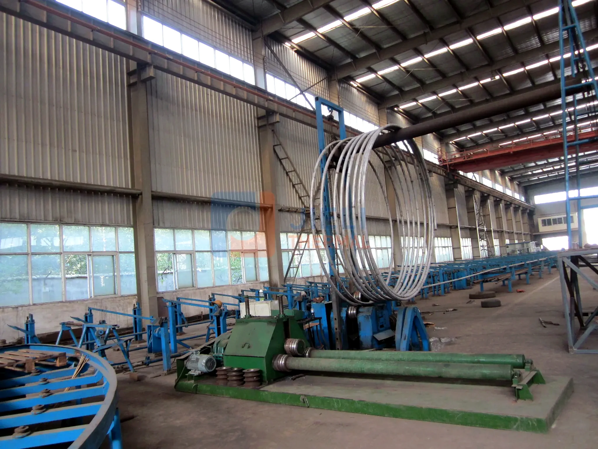
Large helical coils accumulate tolerances. Tube ovality, springback after bending, weld shrinkage, support location and casing alignment can change the actual clearance. Inspection should therefore record the minimum, maximum and circumferential distribution of the gap—not only the nominal drawing value.
Supports must hold the coils concentric while allowing the thermal movements predicted for start-up and operation. The minimum hot-condition clearance must prevent contact and vibration, while the maximum clearance must not create an uncontrolled bypass channel. Access for weld inspection and practical maintenance is part of the geometry, not an afterthought.
08 · COMPLETE-SYSTEM VIEW
Coil spacing is one variable inside a complete heating plant.
The heater, burner, combustion air, induced or forced draft, stack, heat recovery, circulation pumps, expansion system, instruments and control logic determine the operating result together. A very compact coil does not compensate for poor burner matching, insufficient oil flow or an undersized fan.
For reliable operation, the final design should document the calculation basis, expected clean and normal-used pressure drop, fan operating points, commissioning measurements and maintenance limits. These values give operators a meaningful baseline for future troubleshooting.
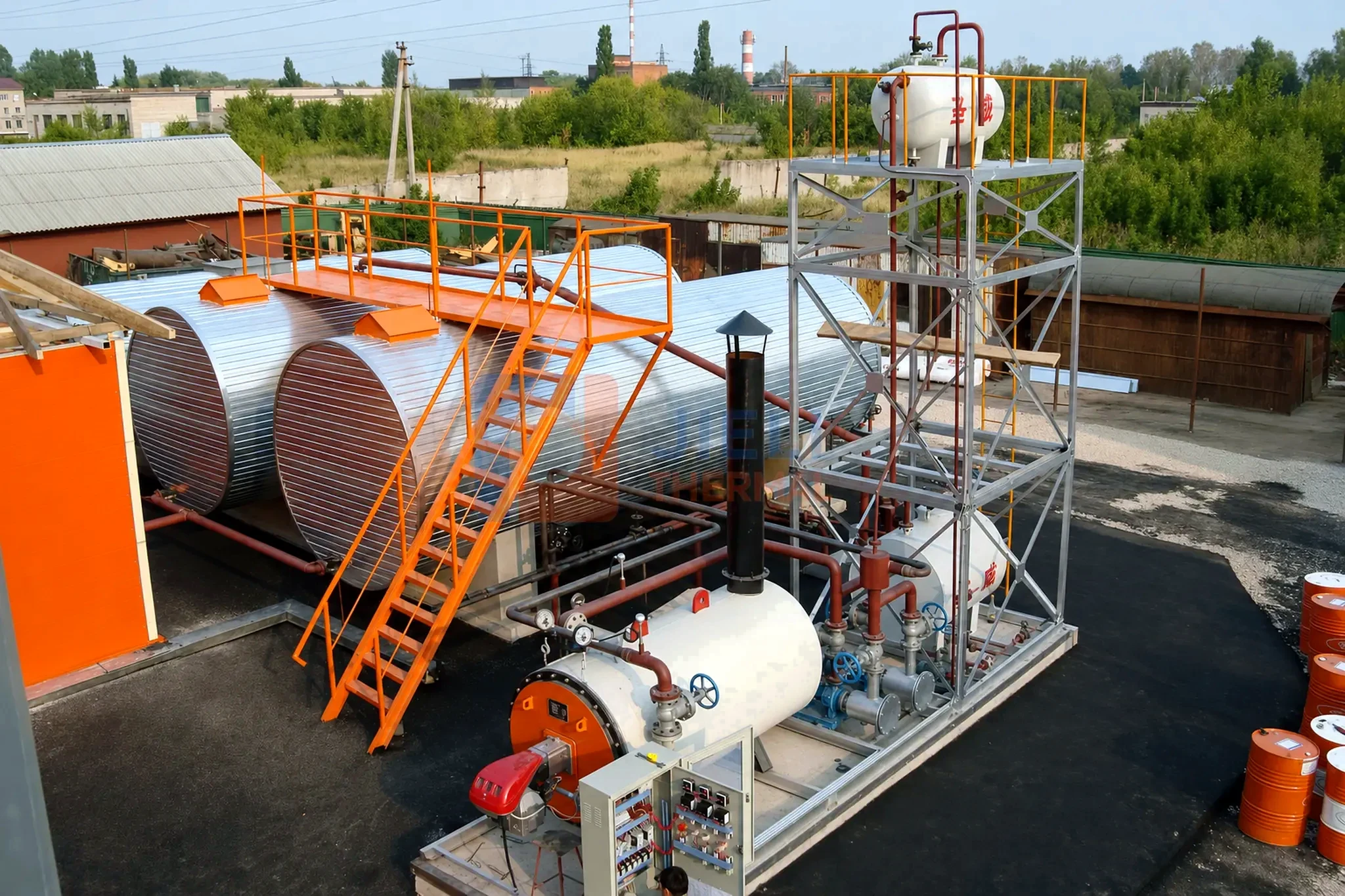
Project information needed to confirm double-coil spacing
- Heat duty, supply/return temperatures and thermal-fluid type;
- Fuel composition, firing range, excess air and emissions requirements;
- Tube OD, coil diameters, active length and proposed turn pitch;
- Flue-gas mass flow, temperature profile and downstream heat recovery;
- Required furnace pressure, fan curves and stack conditions;
- Oil flow, coil pressure drop and maximum film-temperature limit;
- Manufacturing tolerances, thermal expansion and maintenance access.
TECHNICAL REFERENCES
Sources used for this engineering guide.
- Jha, Elgandelwar & Lele — Transient Modeling of a Fired Helical Coil Thermal Oil Heater (2022)
- Chen et al. — Experimental Investigation of Heat Transfer and Pressure Drop Characteristics of H-Type Finned Tube Banks (2014)
- U.S. Department of Energy — Better Plants Fan System Cheat Sheet
- American Petroleum Institute — Fired-heater design scope in API Standard 560
- Combustion Engineering Association — BG07 Thermal Fluid Systems
- FM — Data Sheet 7-99, Heat Transfer Fluid Systems
The references support calculation methods, not a universal 50 mm limit. The H-type finned-tube study concerns a different geometry; do not apply its correlations directly to helical coils.
FREQUENTLY ASKED QUESTIONS
Double-coil spacing FAQ
Is 50 mm a mandatory standard for thermal oil heater coil spacing?
No. It is a practical starting window used in some clean gas-fired double-coil designs, not a universal code value. The final spacing must be calculated for the actual capacity, geometry, fuel, gas flow, fan and operating conditions.
Does a smaller coil gap always improve heater efficiency?
No. A smaller gap can increase gas velocity and convection, but it also raises pressure drop and may reduce fan margin or create maldistribution. The optimum is the best thermal-hydraulic balance, not the smallest dimension.
Is radial double-coil clearance the same as helical turn pitch?
No. Radial clearance is the gap between the inner and outer concentric coil layers. Turn pitch is the axial center-to-center distance between neighboring turns in one helix. Both must be defined and checked separately.
Can the same under-50-mm gap be used for biomass or coal?
It should not be copied automatically. Ash-bearing flue gas introduces fouling, slagging, erosion and cleaning requirements that can require different spacing and gas velocity limits.
How should a final coil spacing be confirmed?
Confirm it through coupled heat-transfer and pressure-drop calculations, burner/fan curve checks, oil-side film-temperature assessment, hot-condition expansion review, manufacturing tolerances and—where complexity justifies it—CFD or validated operating data.
JIELI THERMAL ENGINEERING
Compact where it improves performance. Open where reliability requires it.
Share your heat duty, thermal-oil temperatures, fuel, site conditions and required standard. Our team can review the heater coil, combustion, draft, circulation and controls as one coordinated system.
Discuss your thermal-oil project